ESP32 development notes (two) OLED ssd1306 apds9960 gesture control
tags: ESP32 SSD1306 APDS9960 Gesture control Low power consumption
ESP32 OLED Demo
Source address:GitHub source address
Realize function
The ESP32 OLED demo implements the following functions:
- Temperature and humidity data collection
- Network update real time
- OLED paging display temperature and humidity, real-time time
- Gesture/touch sensor control OLED display page up and down
- Manually enter low power mode via touch sensor
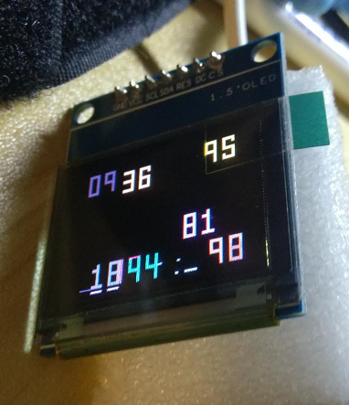
The following picture shows the physical hardware picture of ESP32 OLED Demo:

Hardware composition
The DEMO uses ESP32_Button_Module_V2 as the development board, and contains the following components:
- Proximity/Ambient Light Sensor (APDS9960)
- OLED display (SSD1306)
- Temperature and humidity sensor (HTS221)
- Two touch sensor buttons
Complete hardware schematic diagram:ESP32_BUTTON_MODULE_V2.pdf
Schematic diagram of display screen and sensor power switch control:

VDD33 is the LDO VOUT 3.3V terminal, used as the power supply for ESP32, peripherals, and flash; VDD33_PeriP is the power supply for the display, temperature and humidity sensors, and gesture sensors. Transistor SI2301 is used as a power switch to control the voltage of VDD33_PeriP. By default, the gate terminal of the transistor is kept high and the power switch is turned off. The power switch is turned on by controlling Power_ON to keep it low.
software design
We used the following methods to implement the ESP32 OLED demo:
- Use esp-iot-solution development kit
- Based on FreeRTOS real-time operating system, multitasking
- SNTP protocol to obtain real-time time
- Enter low power mode through touch sensor
- Wake up the device via touch sensor
Low power mode description
Low power mode hardware design
We have used the following methods to minimize the power consumption of the device in low-power mode.
- Control the power switch of the display screen, temperature and humidity sensor, gesture sensor
- Choose low-power LDO, quiescent current is about 1 μA
- Power consumption management for touch sensors
Touch sensor duty cycle
When the touch sensor is working, there are two states: sleep and measurement, the two states cycle alternately. In the normal working mode, we set the sleep time to be relatively short. After entering the low power mode, we set the sleep time to be relatively long to reduce power consumption as much as possible.
Called before entering low power modetouch_pad_set_meas_time(uint16_t sleep_cycle, uint16_t meas_cycle) The interface adjusts the sleep and measure time of the touch sensor.
Parameter Description:
sleep_cycle:sleep_cycleDetermines the interval time between two measurements, the interval time t_sleep = sleep_cycle / (RTC_SLOW_CLK frequency).can use
rtc_clk_slow_freq_get_hz()Interface acquisitionRTC_SLOW_CLKfrequency value.meas_cycle:meas_cycleDetermine the measurement time, the measurement time t_meas = meas_cycle / 8M, the maximum measurement time is 0xffff / 8 M = 8.19 ms.
Low power mode use
Long press the touch sensor button to enter the low-power mode. In the low-power mode, the sampling frequency of the touch sensor will be reduced to the lowest. Therefore, waking up from the low-power mode also requires a little longer to touch the sensor button. The current sampling in low power mode is as follows:
- The current sampling diagram of the LDO VOUT 3.3V terminal in low power consumption mode is as follows (including the current consumed by ESP32, display and sensor):

Note: In low power consumption mode, the average current of LDO VOUT 3.3V is about 30 μA, and the maximum current is about 1.6 mA. When it is at the peak, the touch sensor is in the measurement state.
- The current sampling diagram of the LDO VIN 5V terminal in low power mode is as follows (including the current consumed by ESP32, display, sensor, and LDO):

Note: In low power consumption mode, the average current of LDO VIN 5V is about 45 μA, and the maximum current is about 2.1 mA.
OLED Demo compile and run
Preliminary preparation
First of all, you need to make sure that the ESP32 toolchain has been installed on your computer. For toolchain installation, please refer to the ESP-IDFREADME.md。
Get the IoT Solution project code
Execute the instruction to download the iot-solution project warehouse:
You can directly get the warehouse code recursively, which will automatically initialize all the required submodules:
git clone --recursive https://github.com/espressif/esp-iot-solution.gitYou can also manually initialize the sub-module, first run the following command:
git clone https://github.com/espressif/esp-iot-solution.git- Then switch to the project root directory and execute the following instructions to download some other submodules that this project depends on:
git submodule update --init --recursive
Compile and run
After the submodule code download is complete, the oled_screen_module in the Iot Solution project can be compiled and run. Switch to the esp-iot-solution/examples/oled_screen_module directory, and then perform the following steps.
- Serial port parameter setting
Execute the following commands to compile and configure, such as serial port number and serial download speed can beSerial flasher config Configure in this menu option (if you don’t need to configure, you can skip this step).
    cd YOUR_IOT_SOLUTION_PATH/examples/oled_screen_module
make menuconfig- Compile, flash and run
Execute the following command to compile oled_screen_module. In the following command, flash is the download command, and monitor means to open the system for printing. You can choose to add it according to the actual situation.
make flash monitorNote: When downloading the program, if the download cannot start automatically, you can try to enter the download mode manually. After downloading the firmware, press the reset button on the development board to re-run the program, you can view the serial port print.
Intelligent Recommendation
esp notes (7) to drive the display of OLED (SSD1306)
The development environment of this article: MCU model: ESP8266 IDE environment: Arduino IDE 1.8.9 1.27 inch full color OELD module The content of this article: esp8266 uses u8g2 graphics library to d...

[SCM notes] OLED controller SSD1306 and driver code
Foreword: For a long time, there were few opportunities to use OLED. Even if I used Daniel's code that was also a reference, I had to study it carefully recently. Write it down and forget it. The 0.61...
OLED SSD1306 driver writing
OLED SSD1306 driver writing pit: 1、 The pit is dead, and the "==" priority is higher than the "&". . . . . . . . . 2、(The following things are wrong, with a reminder) The first...
oled display module ssd1306
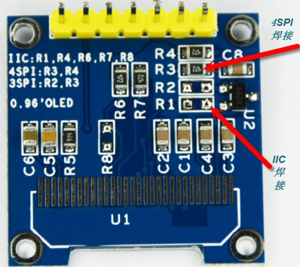
Pin definition GND: power ground VCC: Both 3.3v and 5v power supply are available D0: Serial input clock CLK D1: Serial input data RES: reset DC: Control input data/command (high level 1 is data, low ...
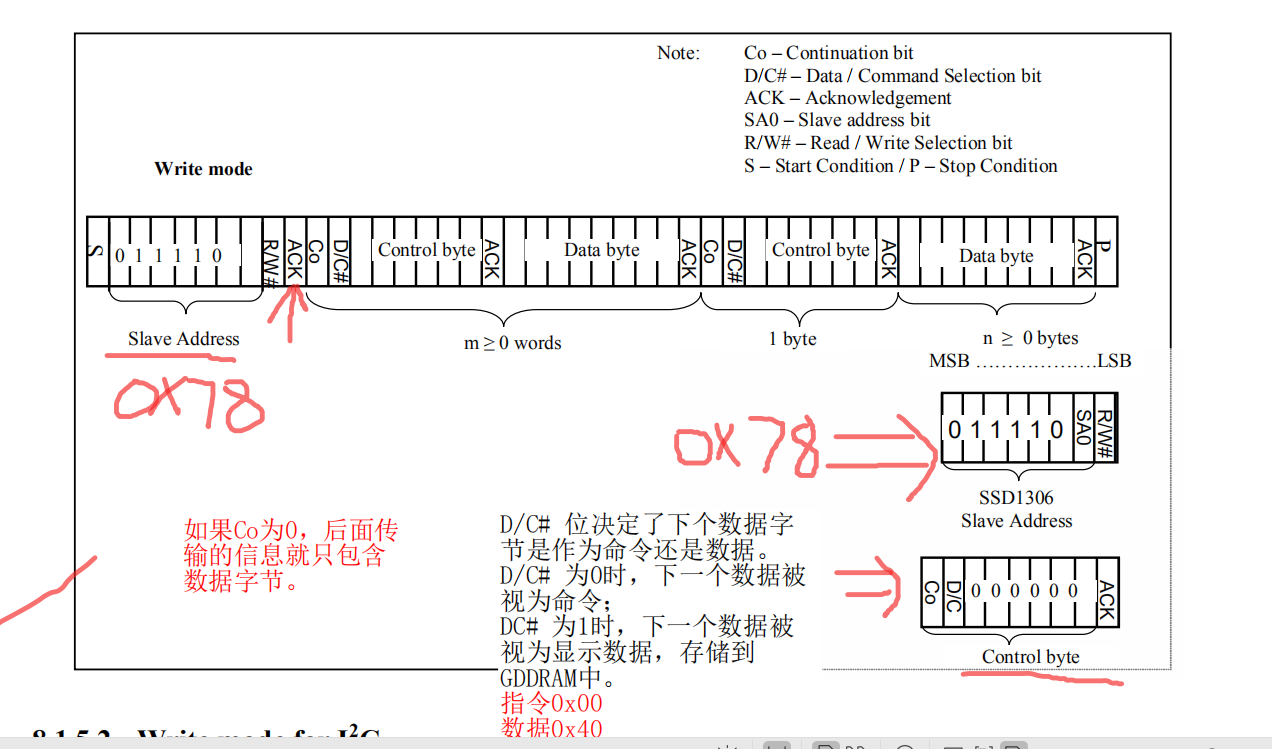
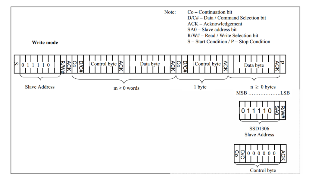
OLED uses SSD1306 IIC
OLED use OLED use 1. Data communication using IIC Communication Protocol 2. OLED function OLED use 1. Data communication using IIC Communication Protocol Software simulation IIC start signal Software ...
More Recommendation
RK3288 lighting OLED SSD1306
Toss LOG There are many OLD drivers written online, here for convenience, directly using SSD drivers in the core 1, wiring RK3288 pin label OLED pin ...

SSD1306 Drive OLED screen
This article will introduce the basic method of using the SSD1306 screen drive chip 1.1 Introduction SSD1306 is a screen drive chip that can be used to drive 128 * 64 pixel OLED. SSD1306 embedded cont...
SSD1306 (OLED)+clock module
When making this alarm clock, you need to make steps. The first step is to light OLED first, Step in the second step to set the clock module time The third step is to adjust the screen font position &...

WIN7+ESP32 + MicroPython Minimal White is the simplest and most feasible graphical tutorial (Part 2, 0.96 OLED LCD SSD1306.)
Good After the previous article, we can already light an LED light. But this is the interpreter running one sentence at a time, so how does the script work? Here is the recommended sharing site for th...