【Micropython ESP32】 SSD1306 0.96 "OLED+Network Clock
tags: Micropython embedded development # MicroPython for ESP32 MicroPython ESP32 ssd1306 OLEd Network clock
【Micropython ESP32】 SSD1306 0.96 "OLED+Network Clock
- This example is based on
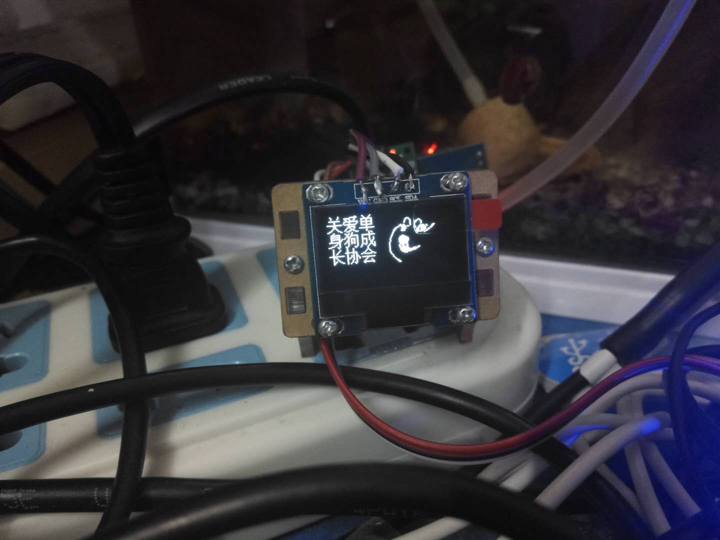
ThonnyPlatform development. - Display effect

Display part
- use
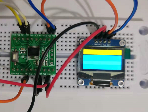
ssd 13060.96 "OLED screen to display time. - Wiring description:
0.96"OLED ----ESP32
SCL  ---- 22
SDA ---- 21
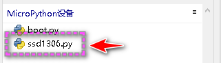
- Before running the debugging code, you need to
ssd1306.pySave it on the Micropython device and run the main code.
SSD1306 module download link ::
- Chinese download station:
https://www.cnpython.com/pypi/micropython-ssd1306/download - Official download station:
https://pypi.org/project/micropython-ssd1306/ ssd1306.pyThe code is as follows; (copy it and save it asssd1306.pyOn the Micropython device)
# MicroPython SSD1306 OLED driver, I2C and SPI interfaces

from micropython import const
import framebuf


# register definitions
SET_CONTRAST = const(0x81)
SET_ENTIRE_ON = const(0xA4)
SET_NORM_INV = const(0xA6)
SET_DISP = const(0xAE)
SET_MEM_ADDR = const(0x20)
SET_COL_ADDR = const(0x21)
SET_PAGE_ADDR = const(0x22)
SET_DISP_START_LINE = const(0x40)
SET_SEG_REMAP = const(0xA0)
SET_MUX_RATIO = const(0xA8)
SET_COM_OUT_DIR = const(0xC0)
SET_DISP_OFFSET = const(0xD3)
SET_COM_PIN_CFG = const(0xDA)
SET_DISP_CLK_DIV = const(0xD5)
SET_PRECHARGE = const(0xD9)
SET_VCOM_DESEL = const(0xDB)
SET_CHARGE_PUMP = const(0x8D)

# Subclassing FrameBuffer provides support for graphics primitives
# http://docs.micropython.org/en/latest/pyboard/library/framebuf.html
class SSD1306(framebuf.FrameBuffer):
    def __init__(self, width, height, external_vcc):
        self.width = width
        self.height = height
        self.external_vcc = external_vcc
        self.pages = self.height // 8
        self.buffer = bytearray(self.pages * self.width)
        super().__init__(self.buffer, self.width, self.height, framebuf.MONO_VLSB, self.width)
        self.init_display()

    def init_display(self):
        for cmd in (
            SET_DISP | 0x00,  # off
            # address setting
            SET_MEM_ADDR,
            0x00,  # horizontal
            # resolution and layout
            SET_DISP_START_LINE | 0x00,
            SET_SEG_REMAP | 0x01,  # column addr 127 mapped to SEG0
            SET_MUX_RATIO,
            self.height - 1,
            SET_COM_OUT_DIR | 0x08,  # scan from COM[N] to COM0
            SET_DISP_OFFSET,
            0x00,
            SET_COM_PIN_CFG,
            0x02 if self.width > 2 * self.height else 0x12,
            # timing and driving scheme
            SET_DISP_CLK_DIV,
            0x80,
            SET_PRECHARGE,
            0x22 if self.external_vcc else 0xF1,
            SET_VCOM_DESEL,
            0x30,  # 0.83*Vcc
            # display
            SET_CONTRAST,
            0xFF,  # maximum
            SET_ENTIRE_ON,  # output follows RAM contents
            SET_NORM_INV,  # not inverted
            # charge pump
            SET_CHARGE_PUMP,
            0x10 if self.external_vcc else 0x14,
            SET_DISP | 0x01,
        ):  # on
            self.write_cmd(cmd)
        self.fill(0)
        self.show()

    def poweroff(self):
        self.write_cmd(SET_DISP | 0x00)

    def poweron(self):
        self.write_cmd(SET_DISP | 0x01)

    def contrast(self, contrast):
        self.write_cmd(SET_CONTRAST)
        self.write_cmd(contrast)

    def invert(self, invert):
        self.write_cmd(SET_NORM_INV | (invert & 1))

    def show(self):
        x0 = 0
        x1 = self.width - 1
        if self.width == 64:
            # displays with width of 64 pixels are shifted by 32
            x0 += 32
            x1 += 32
        self.write_cmd(SET_COL_ADDR)
        self.write_cmd(x0)
        self.write_cmd(x1)
        self.write_cmd(SET_PAGE_ADDR)
        self.write_cmd(0)
        self.write_cmd(self.pages - 1)
        self.write_data(self.buffer)


class SSD1306_I2C(SSD1306):
    def __init__(self, width, height, i2c, addr=0x3C, external_vcc=False):
        self.i2c = i2c
        self.addr = addr
        self.temp = bytearray(2)
        self.write_list = [b"\x40", None]  # Co=0, D/C#=1
        super().__init__(width, height, external_vcc)

    def write_cmd(self, cmd):
        self.temp[0] = 0x80  # Co=1, D/C#=0
        self.temp[1] = cmd
        self.i2c.writeto(self.addr, self.temp)

    def write_data(self, buf):
        self.write_list[1] = buf
        self.i2c.writevto(self.addr, self.write_list)


class SSD1306_SPI(SSD1306):
    def __init__(self, width, height, spi, dc, res, cs, external_vcc=False):
        self.rate = 10 * 1024 * 1024
        dc.init(dc.OUT, value=0)
        res.init(res.OUT, value=0)
        cs.init(cs.OUT, value=1)
        self.spi = spi
        self.dc = dc
        self.res = res
        self.cs = cs
        import time

        self.res(1)
        time.sleep_ms(1)
        self.res(0)
        time.sleep_ms(10)
        self.res(1)
        super().__init__(width, height, external_vcc)

    def write_cmd(self, cmd):
        self.spi.init(baudrate=self.rate, polarity=0, phase=0)
        self.cs(1)
        self.dc(0)
        self.cs(0)
        self.spi.write(bytearray([cmd]))
        self.cs(1)

    def write_data(self, buf):
        self.spi.init(baudrate=self.rate, polarity=0, phase=0)
        self.cs(1)
        self.dc(1)
        self.cs(0)
        self.spi.write(buf)
        self.cs(1)
Instance code
# ESP32 MicroPython Web Clock

import network
import urequests
import ujson
import utime
From SSD1306 Import SSD1306_i2c #Import SSD1306_i2C submissis from the SSD1306 module
from machine import RTC, I2C, Pin

# user data
ssid = "MERCURY_D268G" # wifi router name
pw = "pba5ayzk" # wifi router password

url = 'http://worldtimeapi.org/api/timezone/Asia/Hong_Kong'

web_query_delay = 60000 # interval time of web JSON query
retry_delay = 5000 # interval time of retry after a failed Web query

# SSD1306 OLED display
print("Connecting to wifi...")
i2c = I2C(1,sda=Pin(21), scl=Pin(22),freq=100000)
oled = SSD1306_I2C(128, 64, i2c,addr=0x3c)
oled.fill(0)
oled.text("Connecting", 0, 0)
oled.text(" to wifi...", 15, 16)
oled.show()

# internal real time clock
rtc = RTC()

# wifi connection
wifi = network.WLAN(network.STA_IF) # station mode
while(not wifi.isconnected()):
    wifi.active(True)
    try:
        wifi.connect(ssid,pw)  # wifi network information
        utime.sleep(1.0)
    except OSError:
        print("OSError")
        utime.sleep(2.0)


# wifi connected
print("IP: " + str(wifi.ifconfig()[0]) + "\n")
oled.text("Connected. IP: ", 0, 30)
oled.text(" " + str(wifi.ifconfig()[0]), 0, 45)
oled.show()

# set timer
update_time = utime.ticks_ms() - web_query_delay
# main loop
while True:

    # if lose wifi connection reboot ESP32
    if not wifi.isconnected():

        machine.reset()

    # query and get web JSON every web_query_delay ms
    if utime.ticks_ms() - update_time >= web_query_delay:        # HTTP GET data

        response = urequests.get(url)

        if response.status_code == 200: # query success

            print("JSON response:\n" + response.text)

            # parse JSON
            parsed = ujson.loads(response.text)
			# you can also use parsed = response.json()
            datetime_str = str(parsed["datetime"])
            year = int(datetime_str[0:4])
            month = int(datetime_str[5:7])
            day = int(datetime_str[8:10])
            hour = int(datetime_str[11:13])
            minute = int(datetime_str[14:16])
            second = int(datetime_str[17:19])
            subsecond = int(round(int(datetime_str[20:26]) / 10000))

            # update internal RTC
            rtc.datetime((year, month, day, 0, hour, minute, second, subsecond))
            update_time = utime.ticks_ms()
            print("RTC updated\n")

        else: # query failed, retry retry_delay ms later
            update_time = utime.ticks_ms() - web_query_delay + retry_delay

    # generate formated date/time strings from internal RTC
    date_str = "{:02}/{:02}/{:4}".format(rtc.datetime()[1], rtc.datetime()[2], rtc.datetime()[0])
    time_str = "{:02}:{:02}:{:02}".format(rtc.datetime()[4], rtc.datetime()[5], rtc.datetime()[6])

    # update SSD1306 OLED display
    oled.fill(0)
    oled.text("ESP32 Clock", 20, 0)
    oled.line(0, 14, 128, 14, 1)#
    oled.text("Date: " + date_str, 0, 25)
    oled.text("Time: " + time_str, 0, 45)
    oled.show()

    utime.sleep(0.1)
Replace the API interface
- Suning API interface:
http://quan.suning.com/getSysTime.do
Save the accuracy of milliseconds, but the acquisition is relatively simple.
# ESP32 MicroPython Web Clock
import urequests
import network
#import urequests
import ujson
import utime
From SSD1306 Import SSD1306_i2c #Import SSD1306_i2C submissis from the SSD1306 module
from machine import RTC, I2C, Pin
# user data
ssid = "MERCURY_D268G" # wifi router name
pw = "pba5ayzk" # wifi router password
#url = 'http://worldtimeapi.org/api/timezone/Asia/Hong_Kong'
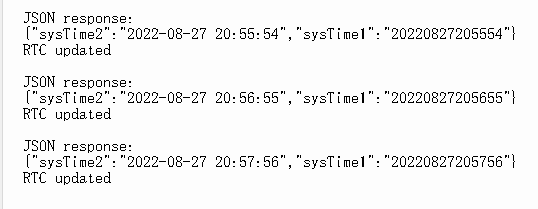
url ='http://quan.suning.com/getSysTime.do'
'''
{"sysTime2":"2022-08-21 13:31:51","sysTime1":"20220821133151"}
'''
web_query_delay = 60000 # interval time of web JSON query
retry_delay = 5000 # interval time of retry after a failed Web query
# SSD1306 OLED display
print("Connecting to wifi...")
i2c = I2C(1,sda=Pin(21), scl=Pin(22),freq=100000)
oled = SSD1306_I2C(128, 64, i2c,addr=0x3c)
oled.fill(0)
oled.text("Connecting", 0, 0)
oled.text(" to wifi...", 15, 16)
oled.show()
# internal real time clock
rtc = RTC()
# wifi connection
wifi = network.WLAN(network.STA_IF) # station mode
while(not wifi.isconnected()):
wifi.active(True)
try:
wifi.connect(ssid,pw) # wifi network information
utime.sleep(1.0)
except OSError:
print("OSError")
utime.sleep(2.0)
# wifi connected
print("IP: " + str(wifi.ifconfig()[0]) + "\n")
oled.text("Connected. IP: ", 0, 30)
oled.text(" " + str(wifi.ifconfig()[0]), 0, 45)
oled.show()
# set timer
update_time = utime.ticks_ms() - web_query_delay
# main loop
while True:
# if lose wifi connection reboot ESP32
if not wifi.isconnected():
machine.reset()
# query and get web JSON every web_query_delay ms
if utime.ticks_ms() - update_time >= web_query_delay: # HTTP GET data 1Update every minute
response = urequests.get(url)
if response.status_code == 200: # query success
print("JSON response:\n" + response.text)
# parse JSON
parsed = ujson.loads(response.text)
# you can also use parsed = response.json()
datetime_str = str(parsed["sysTime2"])
year = int(datetime_str[0:4])
month = int(datetime_str[5:7])
day = int(datetime_str[8:10])
hour = int(datetime_str[11:13])
minute = int(datetime_str[14:16])
second = int(datetime_str[17:19])
# subsecond = int(round(int(datetime_str[20:26]) / 10000))# Milliseconds
# update internal RTC
rtc.datetime((year, month, day, 0, hour, minute, second, 0))
update_time = utime.ticks_ms()
print("RTC updated\n")
else: # query failed, retry retry_delay ms later
update_time = utime.ticks_ms() - web_query_delay + retry_delay
# generate formated date/time strings from internal RTC
date_str = "{:02}/{:02}/{:4}".format(rtc.datetime()[1], rtc.datetime()[2], rtc.datetime()[0])
time_str = "{:02}:{:02}:{:02}".format(rtc.datetime()[4], rtc.datetime()[5], rtc.datetime()[6])
# update SSD1306 OLED display
oled.fill(0)
oled.text("ESP32 Clock", 20, 0)
oled.line(0, 14, 128, 14, 1)#
oled.text("Date: " + date_str, 0, 25)
oled.text("Time: " + time_str, 0, 45)
oled.show()
utime.sleep(0.1)
- SHELL debug window output information
Intelligent Recommendation
micropython esp8266+ssd1306(OLED) display Chinese (example)
1.Adafruit_SSD1306 OLED display library useAdafruit_SSD1306:https://github.com/adafruit/Adafruit_SSD1306 Connection example: Examples of library usage: 2. Display Chinese Code reference:https://github...
[K210 + micropython] Drive SSD1306 OLED Display (I2C)
[K210 + micropython] driver SSD1306 display Article catalog [K210 + micropython] driver SSD1306 display Related knowledge preparation First, I2C and SPI Second, SSD1306 OLED display Third, SSD1306 dri...

[Micropython ESP32] HTTP GET method Get network time+OLED display
[Micropython ESP32] HTTP GET method Get network time+OLED display Effect demonstration This example is based onThonnyPlatform development. Get the relevant timestamp data through the HTTP request GET ...
0.96 -inch OLED screen controller SSD1306 Detailed explanation
In the previous article, the 0.96 -inch OLED screen was driven with a single -chip microcomputer CX32L003 and its lights were realized. 《CX32L003 Light 0.96 inch OLED screen》。 This article will...
More Recommendation
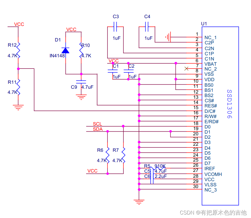
[0.96 OLED screen] schematic diagram and SSD1306 pin function
OLED Screen Schematic OLED Screen Schematic 1. Pin function 2. MCU bus interface pin selection 3. MCU interface selection and allocation 4. MCU serial interface (3-wire SPI) mode 5. MCU serial interfa...

Screen scrolling problem of 0.96-inch OLED (SSD1306 driver chip)
Some questions about Continuous Vertical and Horizontal scrolling setup Just in the morning, one of my classmates adjusted his OLED, and he made a screen scroll horizontally. I said slanderously, let ...
Raspberry Pi 4B port 0.96-inch OLED SSD1306
SDA ==> GPIO 2(pin 3) SCL ==> GPIO 3(pin 5) VCC ==> 3.3V(pin 1) GND ==> GND(pin 14) The above is the hardware wiring diagram Enable I2C interface The I2C interface is disabled by default, ...
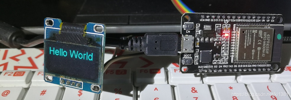
Arduino: Hello World for ESP32 + I2C SSD1306 OLED
I saw a lot of ESP32 introduction articles, fancy its wifi and Bluetooth support, and can also use the Arduino IDE to develop, so itchy, from a treasure into an ESP-WROOM-32 development board to play....

ESP32 Arduino Tutorial: SSD1306 OLED Redrawing String
Introduction The test here is performed on ESP32. The test on ESP32 used DFRobot integrated on FireBeetle ESP32 circuit boardESP-WROOM-32equipment. This esp32 tutorial aims to explain how we use theES...