The overvoltage protection circuit 5v
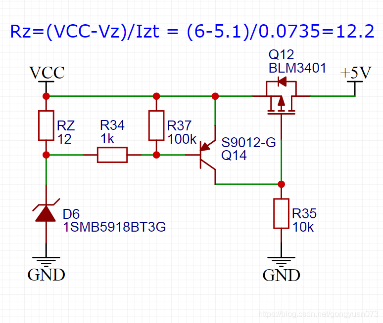
If you want to cut output at 6v can be configured according to the formula to calculate the top, measured 5.8v output cut, but to about 10v when the circuit began to smoke, although it was restored to the 5v to work but still need to continue to adjust the parameters
But a little less than a protective circuit: tubes are normally open, over-voltage on a power zener did not react to the load has been dry dead, Zener response is still too slow
Or directly add TVS forget
Intelligent Recommendation
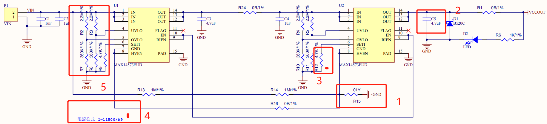
An overcurrent and overvoltage protection circuit for 18650 lithium batteries (using MAX14573 chip)
I recently finished a project and the circuit verification was successful, but there are still some flaws. I want to share it with you. The circuit looks like this: An over-current and over-voltage pr...

Overvoltage protection (2)
Overvoltage protection circuit composed of CW136 The figure shows the overvoltage formed by CW136.protect the circuitWhen the supply voltage of the electronic device exceeds the rated voltage for some...

Overvoltage detection circuit
The schematic diagram of the over-voltage detection circuit is shown in the figure. When an overvoltage signal is generated, the varistor is broken down, showing a low resistance value even close to a...
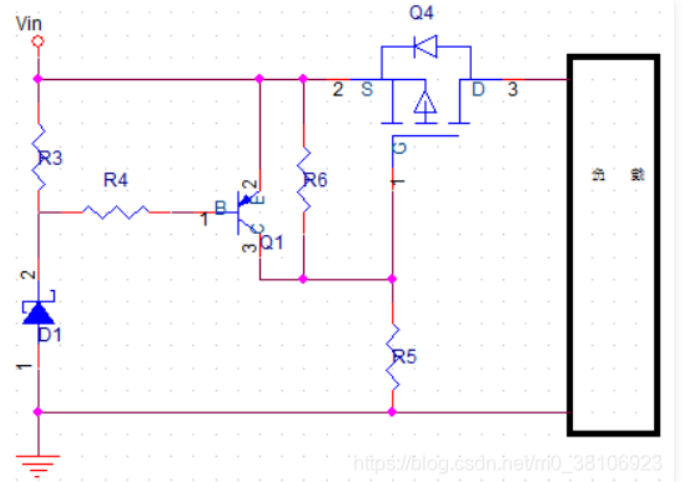
PMOS tube overvoltage circuit
A simple overvoltage protection circuit can generally be realized by adding a TVS. When there is a momentary high-energy impact externally, it can suppress this energy. Although the power is high, tho...
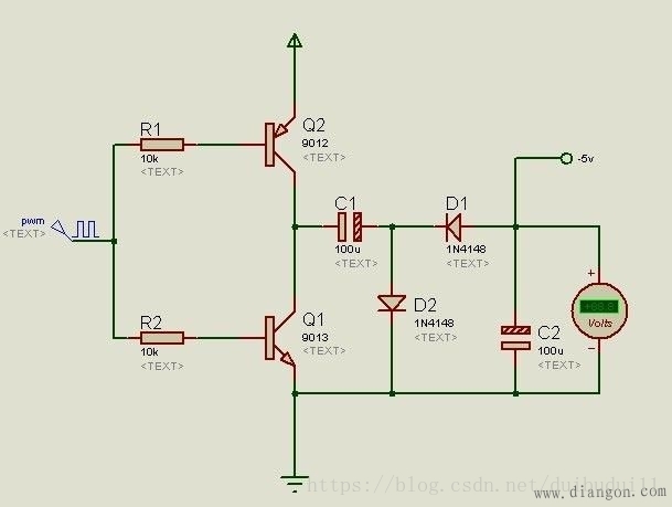
5V + 5V positive voltage to a negative voltage circuit diagram of a 5V-5V
Use positive voltage I do not say, inelectronicCircuit, we often need to use a negative voltage, for example, we often need to give him establish a negative voltage op amp when in use. Here's a simple...
More Recommendation

Simulation of overvoltage circuit formed by triode
Simulation of overvoltage circuit formed by triode This circuit has an overvoltage protection circuit composed of two transistors, four resistors and a Zener diode, as shown in Figure 1: The following...
5V switching circuit Design
Usually PCB circuit may need to involve a switching power supply control portion, may be used at this time the tube P-MOS to control the NPN transistor, wherein the P-MOS tube classic model AO3401, ot...
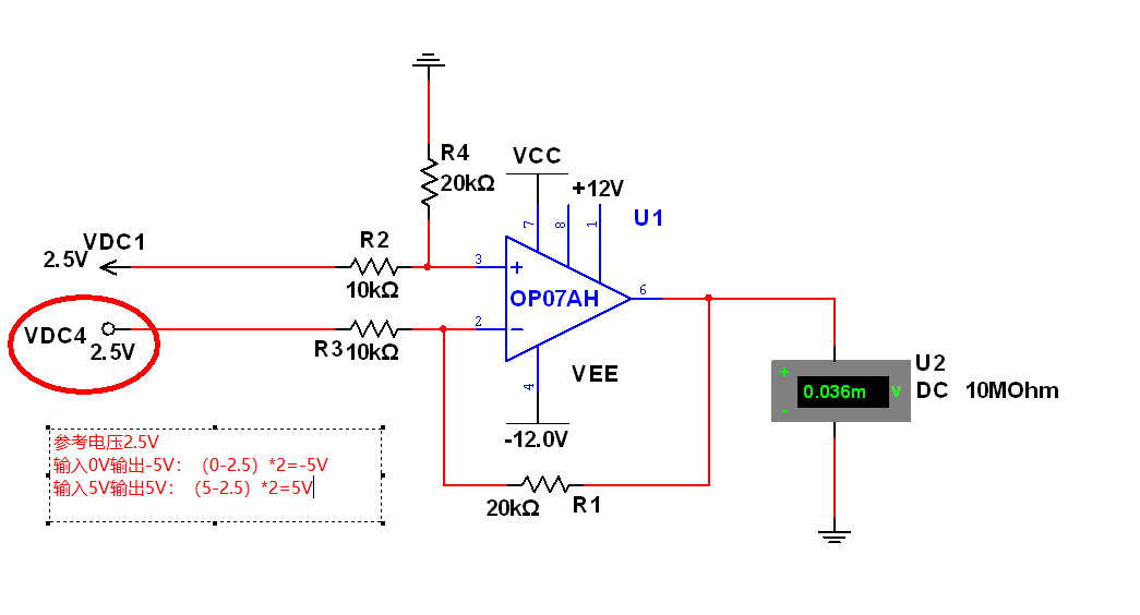
[Subtraction circuit] Realize 0V~+5V input -5V~+5V output
Table of contents The most detailed subtraction circuit analysis on the whole network: PornHub Introduction to the superposition theorem: Basic operation circuit and operation relationship table: Virt...

Power conversion circuit design ---24V to 3.3V or 5V
Externally supplied 7~36V power supply with onboard DC-DC The power chip is converted to a 5V power supply, and the power chip used in the development board is LM2596S-5.0. The chip can output up to 3...

ACM algorithm: Dijkstra's shortest path
Dijkstra's purpose:Dijkstra's algorithm is used to find the shortest path from one node to all other nodes in the graph. Dijes The Tela algorithm is a commonly used algorithm in finding the shortest p...