Overvoltage detection circuit

The schematic diagram of the over-voltage detection circuit is shown in the figure. When an overvoltage signal is generated, the varistor is broken down, showing a low resistance value
even close to a short-circuit state, so that a large current is generated on the primary side of the current transformer, and through the mutual inductance of the coil, it is generated on the secondary side
A small current is converted into a voltage signal through a precision resistor; this signal is input to the voltage comparator LM393,
The voltage comparator LM393 outputs a high level, and the control pulse 2 output by the NOT gate A controls the power circuit and disconnects the switching power supply circuit.
Turn on the backup power supply. The control pulse 1 is sent to the interrupt of the single-chip microcomputer, the single-chip control loop starts the A/D conversion, and samples the transient of overvoltage
Time value.
Intelligent Recommendation
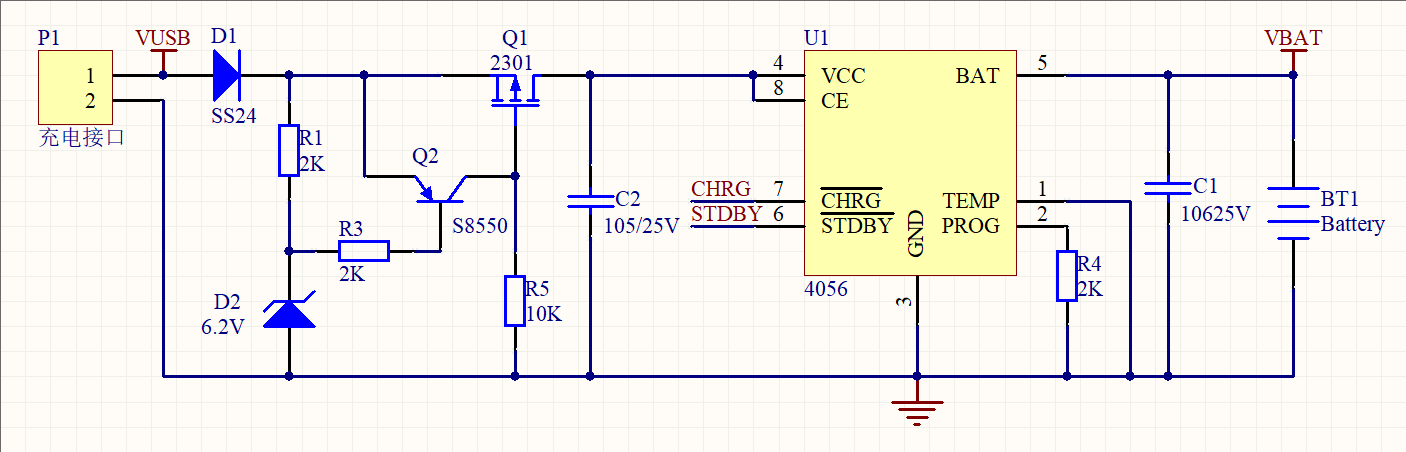
Small appliances - charging overvoltage protection circuit
When the normal 5V input is input,D1 output is about 4.8V, D2 voltage regulator is cut off, the voltage difference between E and B of Q2 is smaller than the on voltage, Q2 is turned off. Q1 is pulled ...
The way of hardware developers-overcurrent, overvoltage and overtemperature protection of protection circuit series
Article from:http://www.eetop.cn/blog/html/65/1196765-6648753.html Summary of the last studyDesign of input power protection in hardware designToday, we will summarize some other protection modules, s...
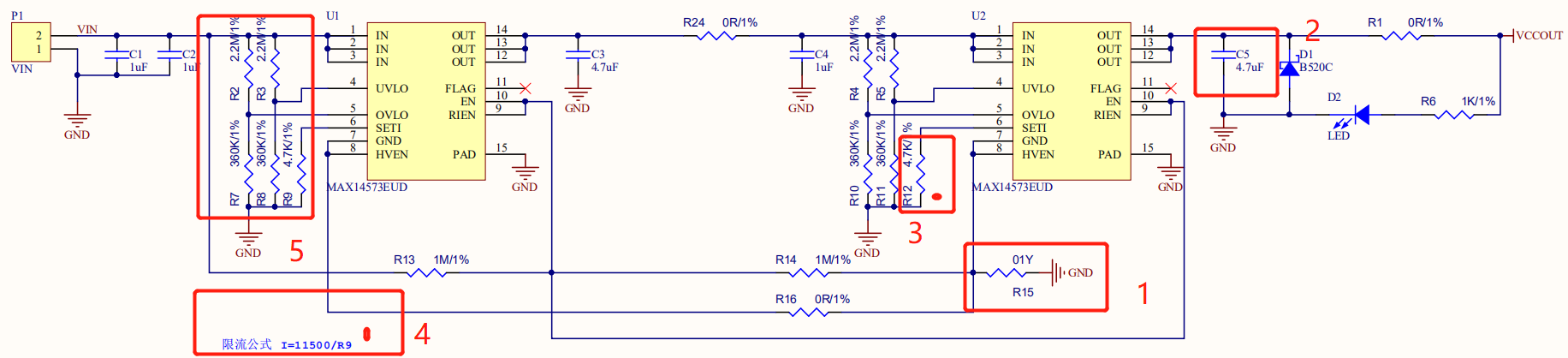
An overcurrent and overvoltage protection circuit for 18650 lithium batteries (using MAX14573 chip)
I recently finished a project and the circuit verification was successful, but there are still some flaws. I want to share it with you. The circuit looks like this: An over-current and over-voltage pr...
Edge detection circuit and code
endmodule Test script code: `timescale 1 ns/ 1 ps module cy4_vlg_tst(); reg eachvec; // test vector input registers reg clk; reg rst_n; reg signal; wire nege_dge; wire pose_dge; cy4 i1 ( ); initial be...

Infrared detection circuit
There are two types of infrared photocells. One is a colorless and transparent LED. This is a transmitting tube. It can generate infrared light that is invisible to the human eye after being ene...
More Recommendation

Edge detection circuit
https://hdlbits.01xz.net/wiki/Edgedetect2 You can directly put combinational logic between two DFFs, streamlining code and resources. Edge detection circuit (edge detection circuit) is a commo...
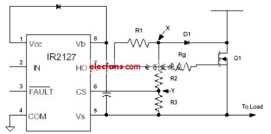
Undersaturation detection circuit diagram
[Introduction]This circuit is a schematic diagram of the undersaturation detection circuit composed of IR2127. Key words:Detection circuit diagramIR2127 This circuit is a schematic diagram of an under...
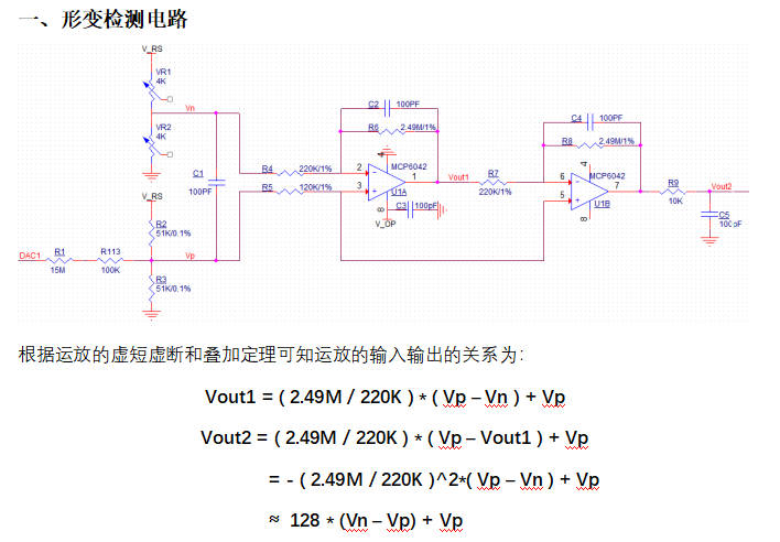
Deformation detection circuit analysis
1. Deformation detection circuits are as follows, VR1 and VR2 are two sensitive gates of resistance strain gates. Expand information: Determination of deformation stress is generally used resistance s...
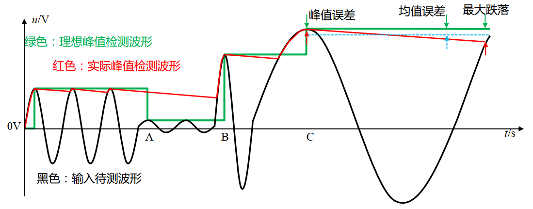
Peak detection circuit
Peak detection circuit concept Peak detection circuit (PKD, peak detector) Concept: Timely discover the positive peak (or negative peak) of the detected waveform, and can immediately output a DC volta...

Usage of edge detection circuit
First, edge edge detection effect? The edge detection is used to detect the rising edge or falling edge of the signal, which is usually used to enable the capture of the signal. Second, useFirst-class...