I2C continuously sends data to the OLED of SSD1306
tags: STM32
When using the OLED driver chip SSD1306, I use I2C communication
When looking at some codes on the Internet, I found that basically every time a byte command/data is sent, a signal, slave address, and a termination signal will be sent immediately after sending. The whole process is like this:
Start signal-send slave address-control byte-data byte-stop signal
Send a command/data related code
void OLED_WR_Byte(u8 dat,u8 mode)
{
	I2C_Start();
	Send_Byte(0x78);
	I2C_WaitAck();
	if(mode){Send_Byte(0x40);}
  else{Send_Byte(0x00);}
	I2C_WaitAck();
	Send_Byte(dat);
	I2C_WaitAck();
	I2C_Stop();
}
But if the initialization needs to send a lot of commands, or when a lot of data needs to be written, it will send a termination signal every time after sending a command/data. Here is initialization as an example.
Initialization related code:
void OLED_Init(void)
{
	OLED_WR_Byte(0xAE,OLED_CMD);//--turn off oled panel
	OLED_WR_Byte(0x00,OLED_CMD);//---set low column address
	OLED_WR_Byte(0x10,OLED_CMD);//---set high column address
	OLED_WR_Byte(0x40,OLED_CMD);//--set start line address  Set Mapping RAM Display Start Line (0x00~0x3F)
	OLED_WR_Byte(0x81,OLED_CMD);//--set contrast control register
	OLED_WR_Byte(0xCF,OLED_CMD);// Set SEG Output Current Brightness
	OLED_WR_Byte(0xA1,OLED_CMD);//--Set SEG/Column Mapping 0xa0 inverted left and right 0xa1 is normal
	OLED_WR_Byte(0xC8,OLED_CMD);//Set COM/Row Scan Direction 0xc0 up and down reversed 0xc8 normal
	OLED_WR_Byte(0xA6,OLED_CMD);//--set normal display
	OLED_WR_Byte(0xA8,OLED_CMD);//--set multiplex ratio(1 to 64)
	OLED_WR_Byte(0x3f,OLED_CMD);//--1/64 duty
	OLED_WR_Byte(0xD3,OLED_CMD);//-set display offset	Shift Mapping RAM Counter (0x00~0x3F)
	OLED_WR_Byte(0x00,OLED_CMD);//-not offset
	OLED_WR_Byte(0xd5,OLED_CMD);//--set display clock divide ratio/oscillator frequency
	OLED_WR_Byte(0x80,OLED_CMD);//--set divide ratio, Set Clock as 100 Frames/Sec
	OLED_WR_Byte(0xD9,OLED_CMD);//--set pre-charge period
	OLED_WR_Byte(0xF1,OLED_CMD);//Set Pre-Charge as 15 Clocks & Discharge as 1 Clock
	OLED_WR_Byte(0xDA,OLED_CMD);//--set com pins hardware configuration
	OLED_WR_Byte(0x12,OLED_CMD);
	OLED_WR_Byte(0xDB,OLED_CMD);//--set vcomh
	OLED_WR_Byte(0x40,OLED_CMD);//Set VCOM Deselect Level
	OLED_WR_Byte(0x20,OLED_CMD);//-Set Page Addressing Mode (0x00/0x01/0x02)
	OLED_WR_Byte(0x02,OLED_CMD);//
	OLED_WR_Byte(0x8D,OLED_CMD);//--set Charge Pump enable/disable
	OLED_WR_Byte(0x14,OLED_CMD);//--set(0x10) disable
	OLED_WR_Byte(0xA4,OLED_CMD);// Disable Entire Display On (0xa4/0xa5)
	OLED_WR_Byte(0xA6,OLED_CMD);// Disable Inverse Display On (0xa6/a7)
	OLED_WR_Byte(0xAF,OLED_CMD);
}
In this way, the transmission of big data is equivalent to most of the useless time spent in the start of sending, sending the slave address and sending the end signal. However, I saw in the SSD1306 Datasheet that it can send data continuously
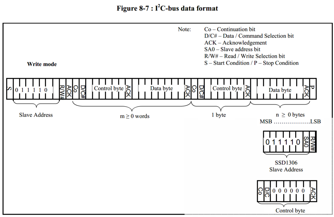
As long as the Co bit of the control byte is changed from 0 to 1, it can be sent continuously
If a command is sent, the control byte is0x00, Change to0x80;
If sending data, the control byte is0x40, Change to0xC0;
Send a control byte, a data byte, and then send a control byte, a data byte...
Attach the code I wrote myself
Send a single byte
ErrorStatus Send_SingleData(uint8_t Data)
{
	SendByte(Data);                           //Send a control byte

	if( NOACK == WaitAck() )                     //The slave does not answer
	{
		I2C_OLED_USART1("No answer from the device");
		I2C_Stop();
		return ERROR;
	}

	return SUCCESS;
}
Send one control byte and one data byte
ErrorStatus Send_TwoData(SENDTYPE Type, uint8_t Data)
{
	if( ERROR == Send_SingleData(Type) )
		return ERROR;
	if( ERROR == Send_SingleData(Data) )
		return ERROR;

	return SUCCESS;
}
Initialize the relevant code, where ContCOMMAND is 0x80;
void I2C_CmdInit(void)
{
	I2C_Start();
	Send_SingleData(I2C_SLAVE_ADDRESS8);

	Send_TwoData(ContCOMMAND,0xAE);// turn off oled panel
	Send_TwoData(ContCOMMAND,0x00);// set low column address
	Send_TwoData(ContCOMMAND,0x10);// set high column address
	Send_TwoData(ContCOMMAND,0x40);//--set start line address  Set Mapping RAM Display Start Line (0x00~0x3F)
	Send_TwoData(ContCOMMAND,0x81);//--set contrast control register
	Send_TwoData(ContCOMMAND,0xCF);// Set SEG Output Current Brightness
	Send_TwoData(ContCOMMAND,0xA1);// Set SEG/Column Mapping
	Send_TwoData(ContCOMMAND,0xC8);// Set COM/Row Scan Direction
	Send_TwoData(ContCOMMAND,0xA6);// set normal display
	Send_TwoData(ContCOMMAND,0xA8);// set multiplex ratio(1 to 64)
	Send_TwoData(ContCOMMAND,0x3f);// 1/64 duty
	Send_TwoData(ContCOMMAND,0xD3);// set display offset	Shift Mapping RAM Counter (0x00~0x3F)
	Send_TwoData(ContCOMMAND,0x00);// not offset
	Send_TwoData(ContCOMMAND,0xd5);// set display clock divide ratio/oscillator frequency
	Send_TwoData(ContCOMMAND,0x80);// set divide ratio, Set Clock as 100 Frames/Sec
	Send_TwoData(ContCOMMAND,0xD9);// set pre-charge period
	Send_TwoData(ContCOMMAND,0xF1);// Set Pre-Charge as 15 Clocks & Discharge as 1 Clock
	Send_TwoData(ContCOMMAND,0xDA);// set com pins hardware configuration
	Send_TwoData(ContCOMMAND,0x12);
	Send_TwoData(ContCOMMAND,0xDB);// set vcomh
	Send_TwoData(ContCOMMAND,0x40);// Set VCOM Deselect Level
	Send_TwoData(ContCOMMAND,0x20);// Set Page Addressing Mode (0x00/0x01/0x02)
	Send_TwoData(ContCOMMAND,0x02);
	Send_TwoData(ContCOMMAND,0x8D);// set Charge Pump enable/disable
	Send_TwoData(ContCOMMAND,0x14);// set(0x10) disable
	Send_TwoData(ContCOMMAND,0xA4);// Disable Entire Display On (0xa4/0xa5)
	Send_TwoData(ContCOMMAND,0xA6);// Disable Inverse Display On (0xa6/a7)
	Send_TwoData(ContCOMMAND,0xAF);
	I2C_Stop();
}
The article is not well written, if you have any questions, I hope everyone can advise
Intelligent Recommendation
SSD1306 (OLED)+clock module
When making this alarm clock, you need to make steps. The first step is to light OLED first, Step in the second step to set the clock module time The third step is to adjust the screen font position &...

OLED data display based on SPI / I2C interface
table of Contents First, display a fixed character Second, showing temperature and humidity Third, slide display long characters Experimental purpose: Understand the principle of OLED screen and the C...
esp8266+oled (ssd1306) driver and display
0x00 OLED change resistance Remove the resistor R3 and solder it to the R1 position; short both ends of R8 with tin, dc and cs pins are grounded; the res pin is controlled by an io to complete the res...
Interpretation of OLED driver chip SSD1306
The driving OLED is actually the driving control chip of the controlled OLED. The commonly used chip SSD1306 and so on. Take this chip as an example to interpret it. It is also my own literacy film as...
ESP32 IDF drive OLED (SSD1306)
Test display screen Reference: Official routines I2C_Tools Readme.md Use IDF Belt Routines I2C_Tools Set I2C pin Detection device address Description hardware is normal 2. Open source drive Stepping r...
More Recommendation
OLED (SSD1306) module display overview
Out Disadvantages of OLED Modules Advantages: small size, high resolution, low pressure 3.3V can work, support multiple interface modes, the module provides a total of four interfaces including: 6800,...
SSD1306 OLED row scanning method
SSD1606 scanning method 2021-12-10 SSD1306 used the page address mode before, and it was changed to the horizontal address mode today Page address mode: Just the column address will increase automatic...
u8g2 SSD1306(I2C) for Z-Stack
The OLED display screen with block SSD1306 128x64 is used, which is used. It is now desirable to drive the OLED display in the Z-Stack CC2530. To let the CC2530 drive OLED display, you need to impleme...
Remember I2C control SSD1306 failed
Project scene:Read the data of all spaces in the flash with a single chip microcomputer, then calculate a checksum on a 0.96-inch OLED driven by SSD1306 (Midjing Park) Problem Description: The ...
SSD1306 (OLED driver IC) Detailed instructions
Basic commands: Column start address set low (Set Lower Column Start Address For Page Addressing Mode) (00h ~ 0Fh) 1. Under page mode address This command is used to set the start address GDDRAM the c...