The relationship between MATLAB SIMULINK, the control cycle, and the sampling frequency (withdress)
Recently, I have encountered problems that need to set up a control cycle in the simulation. I have been shared for a while, and I will share my understanding. Welcome to discuss it together.
The meaning of three concepts
Stepman: Setting up in "Model Configratuon Parameters" above Simulink, see Figure 1 for details. In fact, it is MATLAB to solve differential equations. Δ t \Delta t ΔtThe size, if it is a step-long, Matlab will neglect the steps until the result meets the error requirements; if it is a long way, you can set your own size.
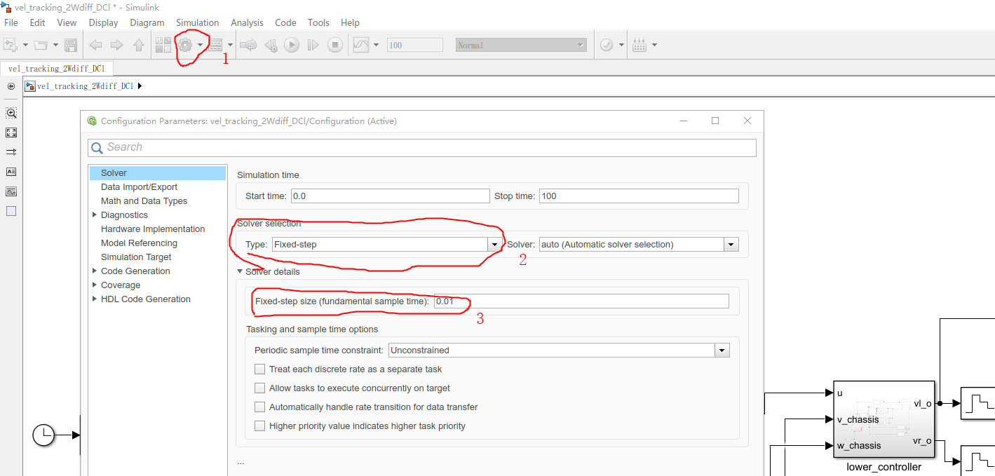
Figure 1 Step length setting
Control cycle: This problem does not encounter in the simulation, but will encounter in actual control. Because the microcontroller responsible for control is not possible to send an instruction from a period of time, there is a control cycle, or the control frequency is used.
Sampling frequency: The core of control is feedback, the controller needs the output of the system to give the next control command, but the system output is a continuous signal, but we need a discrete signal, so it involves the sampling frequency when measurement. That is how long I measure the output of a system.
Three concepts
In general, the step size <sampling cycle <control cycle and preferably an integer multiple relationship (if I am not an error).
Because the step size is a step time, (a bit like the CPU's frequency) is inevitable, the sampling period is small than the control cycle because the control is based on the feedback, and the sampling cycle can add a filter. Eliminate noise.
How do three concepts implement in Simulink simulation?
The step size can be set directly in Simulink. The control cycle and sampling cycle need to be implemented through "Zero-Order Hold".
Figure 2 shows a circuit simulation of the control period of 4 ms, the sampling period is 2 ms, and Fig. 3 is the simulation result. It can be seen that the simulation delay of 0.04s.
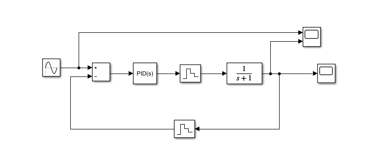
Figure 2: Simulation example
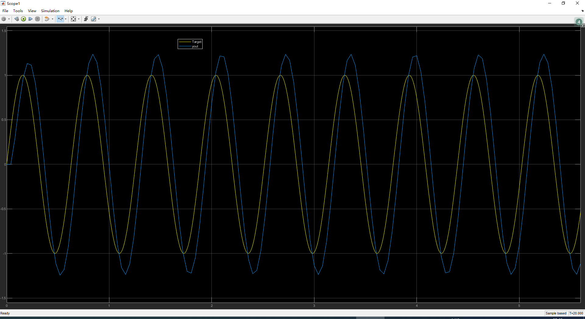
Figure 3: Result curve
Intelligent Recommendation

Call between MATLAB \ Simulink and python
Matlab-Python calling each other PythonIs more and more widely used, and has great advantages in deep learning, machine learning, data mining, etc., and python is open source and has a powerful third-...
Data interaction between MATLAB and Simulink
Simulink is an integrated toolbox of MATLAB for system modeling and simulation. Unlike MATLAB, Simulink's graphical programming function, but when using Simulink, sometimes you need to interact with M...
Simple signal representation and matlab (including sampling frequency
The code comes from Beijing Post MOOC "Signal and System", only for learning summary Representation of discrete signals Unit sample signal Finite length sequence Unilateral exponential seque...
# Matlab # Simple experiment sampling measurement frequency value
Reference connection: https://ww2.mathworks.cn/help/matlab/math/basic-spectral-analysis.html Note: The more the number of waveforms generated, the more the spectrum gets the tips. IncreasettSpectrum c...
Signal and system Matlab time domain sampling and frequency domain sampling
The time-domain sampling theorem gives a constraint condition for signal undistortion in the continuous signal sampling process: for baseband signals, the signal sampling frequency is greater than or ...
More Recommendation
Digital signal processing - Time domain sampling and frequency domain sampling (MATLAB)
Time domain sampling points Ideal Sample Signal of Fourier Transform = Fourier Transform of the Sampling Sequence Frequency domain sampling theorem The frequency domain sampling point N must be greate...
SIMULINK Take the model to do data sampling and do data analysis (MATLAB)
Article catalog Foreword First, Simulink Model Second, MATLAB FUNCTION specific code explanation Source code Foreword This algorithm is a set of numbers (t_INER) before the current time before a set o...
The relationship between the analog frequency and the digital frequency of the signal
The relationship between the analog frequency and the digital frequency of the signal 1. Concept and Definition Analog frequency f: the number of cycles of signal change per second, the unit is Hz, wh...
Simulink simulation of MATLAB-PID control example
Basic PID control 1. Control requirements The controlled object is a second-order linear transfer function of 133 / (s ^ 2 + 25s) The generated signal is sinusoidal signal y = A * sin (2 * pi * Ft) Pr...
Use MATLAB program, Simulink to simulate the control system
1. Use Simulink to establish system simulation Establish the first-order and second-order system control models as shown in the figure. The parameters can be set by double-clicking on the Zero-Pole. T...