4~20ma current to voltage
tags: Circuit design
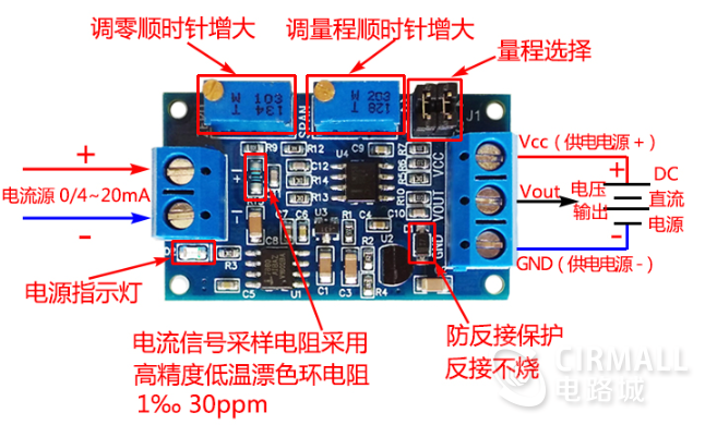
■With anti-reverse power connection function, the module will not be burned when the power supply is reversed. Basically, Taobao similar products do not have this function.
■Zero point and range can be adjusted. Rotate the zero adjustment knob to convert the lower limit of any input current to 0V, and rotate the range knob to convert the upper limit of any input current to the highest voltage required. For example, the current input is 2-17ma, when the input is 2ma, adjusting the zero adjustment knob can adjust the output voltage to 0V, when the input is 17ma, adjusting the range knob can adjust the output voltage to the maximum voltage you need.
■With isolation properties, the power supply that generates 4-20ma current can be different from the module power supply and not share the same ground; it can also be the same power supply and share the ground.
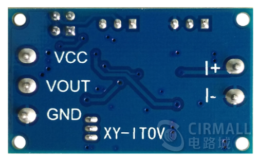
■It can be directly connected with the single-chip microcomputer with AD function (Friendly reminder: the power supply of the single-chip microcomputer should be the same as the module power supply or use the same power supply)
■Simple wiring and high precision
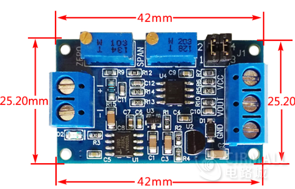
■Length 43mm, width 22mm
■Provide specific size and PCB packaging
■Accuracy grade: 0.2 (5V range)
■Linearity: 0.118% (5V range)
■SMD components in the module are all welded by machine, and the solder joints are smooth and without false soldering.
■The relationship between input current and output voltage: Y is voltage V, X is current ma
Y=X*2.5/16-2.5/4 (4-20ma to 0-2.5V)
Y=X*3.3/16-3.3/4 (4-20ma to 0-3.3V)
Y=X*5/16-5/4 (4-20ma to 0-5V)
Y=X*10/16-10/4 (4-20ma to 0-10V)
Y=X*15/16-15/4 (4-20ma to 0-15V)
Y=X*2.5/20 (0-20ma to 0-2.5V)
Y=X*3.3/20 (0-20ma to 0-3.3V)
Y=X*5/20 (0-20ma to 0-5V)
Y=X*10/20 (0-20ma to 0-10V)
Y=X*15/20 (0-20ma to 0-15V)

product category
This module converts 0-20mA or 4-20mA current into voltage in the range of 0-2.5V/0-3.3V/0-5V/0-10V/0-15V/0-24V;
Product Features
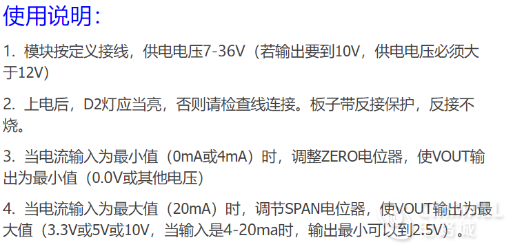
- Power supply voltage range: DC 7~30V;
- Output voltage signal: 0-2.5V/0-3.3V/0-5V/0-10V/0-15V/0-24V;
- Input current range: 0-20mA or 4-20mA;
- Voltage output zero point adjustment: adjustment module 103 potentiometer;
- Voltage output range adjustment: adjustment module 104 potentiometer;
- Isolation nature: op amp isolation;
- Module size: 2.6*4CM;
Working principle analysis
Industrial sensors often use the magnitude of current to transmit data, so as the receiver of sensor data, such as a single-chip microcomputer, a single-chip with internal AD can detect the magnitude of voltage, then the current signal must first be converted into a voltage signal, and then the voltage amplitude must be converted. It is suitable for the voltage range handled by the MCU.
Below we will analyze step by step from the circuit schematic diagram of the designed current-to-voltage module.
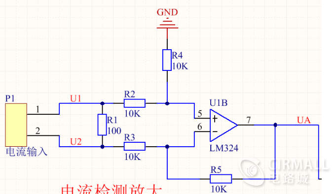
First of all, let's look at the current detection and amplification part, which is the U1B part. The current flows in from the upper end of R1 and flows out from the lower end. It is not difficult to see that this is a differential amplifier circuit, that is, a subtraction circuit, the output voltage UA=(R5/R3)*(U1-U2)=U1-U2, UA is the voltage difference between the two ends of the resistor R1, if it flows through The current of the resistor is 20mA, then the generated voltage is 20*100=2000mV, which has not reached the voltage measurement range of our single-chip microcomputer (here the default detection range of the single-chip AD is 0-5V), so in order to efficiently use the range of the single-chip AD , We need to further amplify the voltage signal. Some people may ask: How to make the current signal input 4mA, then the voltage output is 0V? The key point of this problem is that we want to output a 0V voltage, here we still need to use a subtractor as shown below:
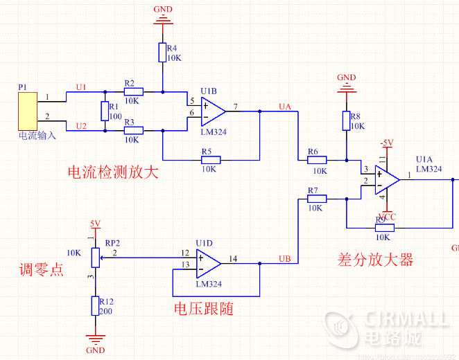
The U1A composition in the figure is a subtraction circuit, and its output voltage is equal to UA-UB. U1D forms a follower, when the current signal is 4mA, UA=4*100=400mV, then the output of U1A is 0V at this time, which is our purpose, then we need UA=UB, then adjust the positive phase of U1D follower The input end can be changed by adjusting the potentiometer RP2 to change the partial pressure. This perfectly solves the problem that the output voltage is 0 when the input current is 4mA. Next, we need to add an amplifier circuit to amplify the output signal of U1A. As shown below:
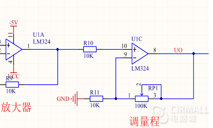
The role of U1C here is the final amplification, so when using, when the input current is set to 20mA, adjust the RP1 potentiometer, that is, adjust the voltage amplification factor, until the output voltage is 5V or other ranges of 10V, 15V, it can be completed The setting of the range.
Setting matters before use:
Zero adjustment: When the input current is 4mA, adjust the zero adjustment potentiometer until the output voltage is 0V.
Range adjustment: When the input current is 20mA, adjust the range adjustment potentiometer until the output voltage is the target range voltage.
The following is the overall circuit diagram of the module:
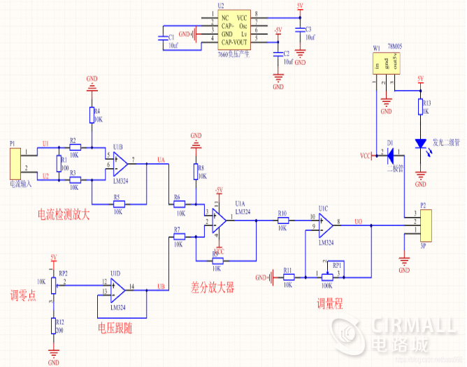
We see that the op amp used in the picture is LM324. This op amp is not a rail-to-rail op amp, so the lowest output voltage of the op amp cannot be equal to 0V. Even if it is a rail-to-rail op amp, the lowest output will still be mV. Level voltage, then we can change the power supply to positive and negative power to solve the problem that the minimum output is not 0V, so use the ICL7660 chip to generate a negative 5V voltage as a negative power supply. The D1 diode in the picture plays a role in preventing reverse connection of the power supply
Intelligent Recommendation
Voltage source and current source
Author: Patrick Zhang link: https://www.zhihu.com/question/35921760/answer/224407660 Source: Knowing Copyright is owned by the author. For commercial reprint, please contact the author for authorizati...
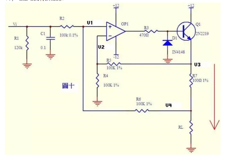
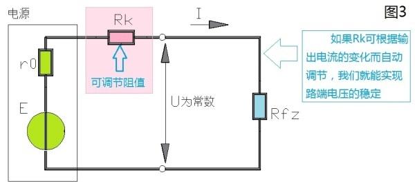
Voltage current conversion detection
Current can be converted into voltage, and voltage can also be converted into current. Figure 10 is such a circuit. The negative feedback in the above figure does not directly feedback through the res...

Current and voltage PHY
The network port PHY chip has voltage driving and current driving for the driving modes of TX and RX.The easiest way to recognize is to look at its recommended schematic, If the center tap of the netw...
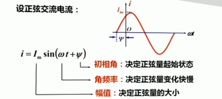
Sinusoidal voltage and current
Alternating current: The electromotive force, voltage, and current whose direction and size change with time are collectively referred to as alternating current. Sinusoidal alternating current: AC pow...
Leading and lagging of voltage and current
attention,Star publicnumber, Do not miss the exciting content Source: Circuit design skills Since Sin[ωt] will appear Sin[ωt±90°] after derivation or integration, for the induct...
More Recommendation

LED voltage drop, current
In-line super bright LED drop There are three main colors with different pressure drops, as follows: Voltage drop of red LED 2.0-2.2 V Voltage drop of yellow LED 1.8-2.0 V Voltage drop of green LED 3....
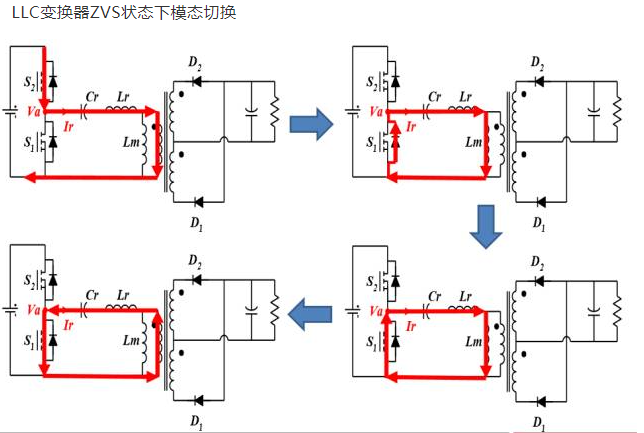
Zero voltage current switch
PWM switching power supply is operated by hard switch mode (the voltage drop / rising and current rise / down / down waveform is overlapped), and therefore the switching loss is large. Although high f...
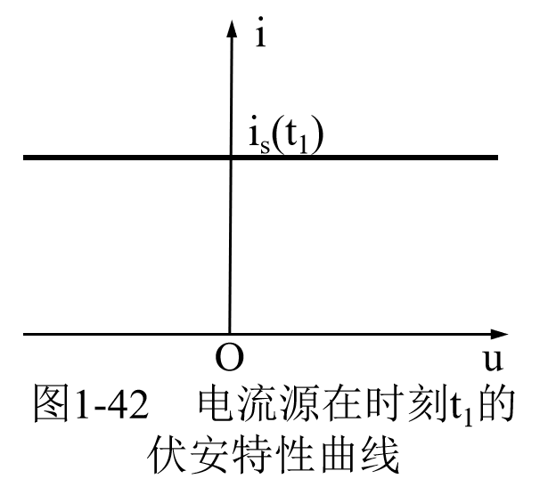
Current source and voltage source
Voltage source (active): is an ideal set-general component such as power supply such as actual batteries. No power circuit iscan not work Voltage source hastwoBasic nature: (1) Its end voltage is the ...
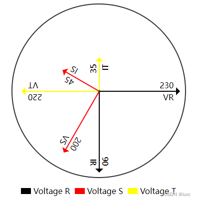
[Voltage, current pointer diagram]
** Simple native HTML creates a pointer diagram of voltage, current ** Due to the small needs of other departments in the work, a small pointer is made. Effect map: code show as below:...
Voltage and current leading and hysteresis
What is the lead and hysteresis of voltage and current Original address The concept of voltage and current advancement and hysteresis is discussed relative to the relationship between current and volt...