1-Analysis of SIM card reset ATR
tags: SIM
Activation timing

At the end of the activation process (the RST in the interface device is in the L state, the VCC is powered on, the I/O enters the receiving mode, and the CLK has been provided with a matching and stable clock signal), the card is ready for cold reset. The internal state of the card before cold reset is not specified.
According to Figure 1, the clock signal is applied to CLK at time Ta. The card should set the I/O to H state within 200 clock cycles (ta delay) after the clock signal is applied to CLK (at the time point of Ta+ta). Cold reset is the result of maintaining RST for at least 400 clock cycles (tb time delay) after the clock signal is applied to CLK (at the time point of Ta+tb). The interface device shall ignore the state on the I/O when RST is in the L state.
At time Tb, RST is set to H state. The response on I/O should start between 400 and 40000 clock cycles (tc time delay) after the rising edge of the signal on RST (at the time point of Tb+tc). If the response does not start within 40,000 clock cycles after the RST is in the H state, the interface device shall perform a deactivation.
void SIM_Cold_Reset(uint8_t ChannelID)
{
    Set_Sim_Io(ChannelID, SIM_VCC, 1);    //In the initial stage, the power supply voltage is powered on first
    Delay_400_CLK();                      //Wait for the voltage to stabilize
    Set_SimData_Direction(ChannelID, 1);  //Set the I/O port to receive mode
    Set_SimClk_Status(ChannelID, 1);      //Start the independent baud rate generator to start counting, and divide the system clock to output
    Delay_400_CLK();                      //RST reset signal needs to keep low level within 400 clock cycles after CLK signal is provided
    Set_Sim_Io(ChannelID, SIM_RST, 1);    //It can be set to high level afterwards
}
Taking the 4M clock as the reference, one clock is 1/4us, then 400 clocks use 100us, and 40,000 clocks are 10ms.
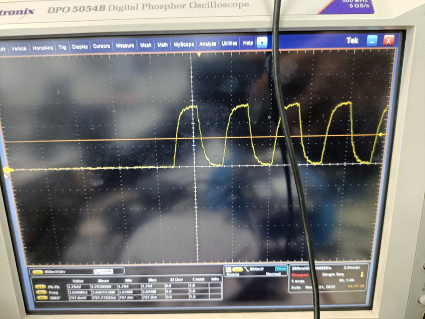
The basic ATR response data is as follows
BelowATR:3B9F94801FC78031E073FE21135758485553494D01F9As an example, explain
| Data element | Description |
|---|---|
| TS | Start character |
| T0 | Format character |
| TA1,TB1,TC1,TD1,… | Interface character |
| T1,T2,… ,TK | Historical characters |
| TCK | Check character |

1. Starting character TS
TS is a mandatory part of ATR and must always be sent. Only two encodings are allowed for this byte: 3B is the forward convention, and 3F is the reverse convention. When using the reverse logic convention, the low-level state of I/O is equivalent to logic 1, and the highest bit of the data byte is sent first after the start bit. When using the forward logic convention, the high-level state of the I/O is equivalent to logic 1, and the lowest bit of the data byte is sent first after the start bit.
The TS of the ATR in the above example is3B2. Format character T0
The format character T0 contains a set of bits indicating which interface character will be transmitted, and it also indicates the number of subsequent historical characters. Like TS, this byte must be present in every ATR.
The high nibble (b5-b8) indicates whether the subsequent characters TA1 to TD1 exist. (B5 corresponds to TA1, b8 corresponds to TD1);
The lower nibble (b1-b4) indicates the number of optional historical characters (0 to 15);
The T0 of the ATR in the above example is9F
 Indicates the existence of TA1 and TD1, the historical characters are15One.
When there is no TD1, T=0, then TCK does not exist.
3. Interface characters TA1, TB1, TC1, TD1,...
These bytes are optional in ATR and are determined by the high nibble of the format character T0.
3.1 Global interface character TA1
The high nibble FI of TA1 is used to determine the value of F, and F is the clock rate conversion factor. Used to modify the clock frequency provided by the terminal after the answer to reset. The low nibble DI is used to determine the value of D, and D is the bit rate adjustment factor. Used to adjust the bit duration used after the answer to reset. etu =F/D * (1/f)
FI and DI codes are as follows:
| FI | F | DI | D |
|---|---|---|---|
| 0000 | 372 | 0000 | RFU |
| 0001 | 372 | 0001 | 1 |
| 0010 | 558 | 0010 | 2 |
| 0011 | 744 | 0011 | 4 |
| 0100 | 1116 | 0100 | 8 |
| 0101 | 1488 | 0101 | 16 |
| 0110 | 1860 | 0110 | 32 |
| 0111 | RFU | 0111 | RFU |
| 1000 | RFU | 1000 | 12 |
| 1001 | 512 | 1001 | 20 |
| 1010 | 768 | 1010 | RFU |
| 1011 | 1024 | 1011 | RFU |
| 1100 | 1536 | 1100 | RFU |
| 1101 | 2048 | 1101 | RFU |
| 1110 | RFU | 1110 | RFU |
| 1111 | RFU | 1111 | RFU |
The TA1 of the ATR in the above example is94
 Show that F=512,D=8。
3.2 Global interface character TB1: (no meaning anymore)
TB1 transmits the values of PI1 and II. PI1 is defined in bits b1 to b5 to determine the programming voltage P value required by the IC card; II is defined in bits b6 and b7 to determine the maximum programming current required by the IC card I value. Generally, ATR must contain TB1=00, which means that the IC card does not use VPP.
TB1 of the ATR in the above example is empty3.2 Global interface character TC1: (no meaning anymore)
TC1 of the ATR in the above example is empty3.2 Global interface character TD1
The TD1 character is more critical. Looking at the ATR data structure diagram above, we can see that the upper 4 bits of TD1 determine whether there is TA2/TB2/TC2/TD2.
In the same way, the upper 4 bits of TD2 determine whether there is TA3/TB3/TC3/TD3.
The TD1 of the ATR in the above example is80,
 Can indicate the existence of TD2=1F, TA2, TB2, TC2 do not exist

 The TD2 of the ATR in the above example is1F,
 It can show that TA3=C7 exists, and TB3, TC3, and TD3 do not exist
4. Historical characters
For a long time, there was no standard for historical characters. The result is that it varies with the operating system manufacturer, and they contain widely varying data.
The historical characters of the ATR in the above example are
8031E073FE21135758485553494D01。
5. Check character TCK
TCK has a value to check the integrity of the data sent during the response to reset. The value of TCK should make all bytes from T0 to including TCK goXORThe result is zero.
When there is no TD1, T=0, then TCK does not exist.
If only the T=0 protocol is indicated in the ATR, the TCK checksum may not appear at the end of the ATR. In this case, it is not sent at all, because the error byte is already known by parity and it is mandatory to send the error byte repeatedly in the T=0 protocol. On the contrary, in the T=1 protocol, the TCK byte must appear, and the checksum calculation starts from byte T0, ends at the last interface character, and if there is, it is the last historical character.
The TCK of the ATR in the above example is F9,
will9F94801FC78031E073FE21135758485553494D01 XOR processing can get F9for(atrCount = 1; atrCount <21; atrCount++)
{
printf("atrXOR_old:%X,atr:%X\n",atrXOR,atr[atrCount]);
atrXOR ^= atr[atrCount];
printf("atrXOR_new:%X\n",atrXOR);
}The analysis of the ATR is as follows:
ATR:3B9F94801FC78031E073FE21135758485553494D01F9
ATR analysis:
 Forward convention F=512 D=8 N=0(d)
Protocal=TO
AtrBinarySize=22
AtrHistorySize=15
AtrHistorySize=8031E073FE21135758485553494D01
31: Card Data Service
 E0: Selection by direct application of the full DF name, and selection of data objects by partial DF names are valid in the DIR file
73: Card capability label
 FE: DF selection (by full DF name, part of DF name, path, file identification)
 EF management (supported short EF identifier, supported record number)
21: Data encoding type
13: Maximum number of logical channels4
TS=3B
T0=9F
TA1=94
TD1=80
TD2=1F
 TA3=C7 (clock stop rest character: no priority level indicator: A, B, and C)
TCK=F9
reference
Intelligent Recommendation
Boot setting card 1 is the default SIM card for sending a text message
Set the location of the short message to send the default SIM card framework/base/telephony/java/android/telephony/DefaultSmsSimSettings.java Add in IF (Subinfos.size ()> 1) {}...

DE-SIM Example Analysis (1) RandomWalk
DE-SIM is a Python-based, open source, object-oriented discrete event simulation tool, and Python can be installed through PIP. DE-SIM will report an error in the case of Windows. For details, please ...
A smart watch SIM card does not recognize the problem analysis
Author: AirCity 2020.3.1 [email protected] owned by all the authors, Aircity Review Questions The problem occurs on a project MTK platform for low-end, mass production machine has a 10% probability ...
Hardware problem record - SIM card cannot be recognized abnormal analysis
1. Background: Usually the SIM card needs to consider the interference of the radio frequency signal transmitted by LTE, and a capacitor of 10-33pf will be used to reduce the impact of interference, s...
[SIM card] Sim card hot swap
3.1. Brief introduction of hot plug function For non-hot-swappable projects, the card-checking process will only be started when the modem is turned on. If the card is not detected at boot time, the c...
More Recommendation

Micro-SIM card and Mini-SIM card
Regarding the Micro-SIM card, in fact, from a technical point of view, there is no essential difference between the Micro-SIM card and the Mini-SIM card. The only difference lies in the surface area, ...
SIM card pin definition
Transfer from: The commonly used SIM card holder is 6 feet, as shown in the figure (web screenshot): The pin used by is: SIMVCC; SIMRST; SIMCLK; SIMDATA (I/O); SIMGND; VPP can be left floating; The ge...
Identification for SIM card
mainly uses:...
SIM card lock
SIM card lock Android is a new way to explore, and God can skip it directly. Original works, please indicate the source! ! ! ! (The content is relatively low-level, I don’t believe that someone ...