OpenGL coordinate system
tags: 3D Math Basic OpenGL
In order to transform the coordinates from one coordinate system to another, we need to use several transformation matrices
- Local Space (Local Space, or Object Space)
- World Space
- View Space (or Eye Space)
- Clip Space
- Screen Space
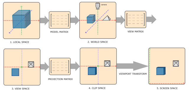
Vertex coordinates start from Local Space, here it is called Local Coordinate, which will become World Coordinate later,
View Coordinate, Clip Coordinate, and finally end in the form of Screen Coordinate.
- Local coordinates are the coordinates of the object relative to the local origin, and are also the coordinates of the starting point of the object.
- Transform local coordinates into world space coordinates, which are in a larger space.
- Transform world coordinates into observation space coordinates so that each coordinate is viewed from the perspective of the camera or observer.
- After the coordinates reach the observation space, they need to be projected to the cropping coordinates. The cropping coordinates will be processed to the range of -1.0 to 1.0, and determine which vertices will appear on the screen.
- Finally, the crop coordinates are transformed into screen coordinates, and a process called Viewport Transform will be used. Viewport transformation transforms the coordinates in the range of -1.0 to 1.0 into the coordinate range defined by the glViewport function. The final transformed coordinates will be sent to the rasterizer and converted into fragments.
Orthographic projection
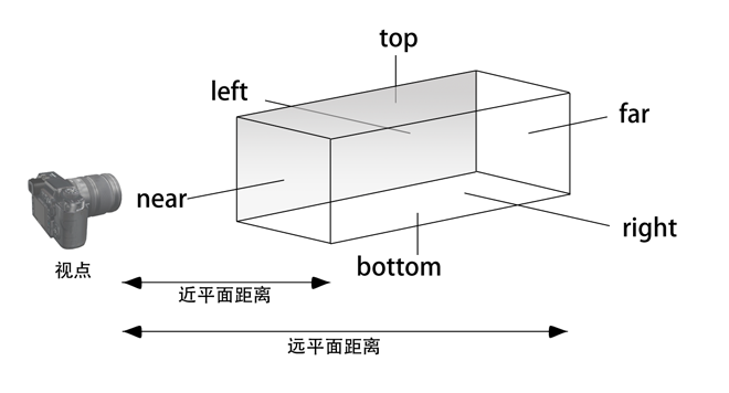
Orthographic projection defines a cube-like truncated avatar box (clipping space), and vertices outside this space will be clipped;
The frustum above defines the visible coordinates, which are specified by the width, height, near (Near) plane and far (Far) plane.
Perspective projection
The projection matrix maps the given frustum range to the clipping space. In addition, the w value of each vertex coordinate is modified, so that the w component of the vertex coordinate further away from the observer is greater; transform to crop The coordinates of the space will be in the range of -w to w; OpenGL requires that all visible coordinates will fall in the range of -1.0 to 1.0 as the final output of the vertex shader.
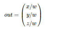
Perspective division will be applied to the coordinates of the clipping space. Each component of the vertex coordinates will be divided by its w component. The farther away from the observer, the smaller the vertex coordinates.
glm::perspective(glm::radians(45.0f), (float)width/(float)height, 0.1f, 100.0f);
A. The first parameter defines the value of fov, which represents the field of view and sets the size of the observation space.
If you want a real observation effect, its value is usually set to 45.0f, but if you want a doom-style result, you can set it to a larger value.
B. The second parameter sets the aspect ratio, which is obtained by dividing the width of the viewport by the height.
C. The third and fourth parameters set the frustumnearwithfarflat. We usually set the close distance to 0.1f and the long distance to 100.0f. All vertices in the near plane and far plane that are inside the frustum will be rendered.
The coordinates of a vertex will be transformed into cropping coordinates according to the following process:

Note that the order of matrix operations is reversed (remember that we need to read matrix multiplication from right to left). The final vertex should be assigned to the vertex shader, gl_Position, and OpenGL will automatically perform perspective division and cropping.
Viewport transformation
The output of the vertex shader requires that all vertices are in the clipping space, which is what we just did using the transformation matrix. OpenGL thenCrop coordinatescarried outPerspective divisionTo transform them toStandardized equipment coordinates. OpenGL uses parameters inside glViewPort to map standardized device coordinates toScreen coordinates, Each coordinate is associated with a point on the screen
Observation space
When the observation space is based on the camera's perspective as the origin of the scene, the coordinates of all the vertices in the scene: the observation matrix transforms all the world coordinates into observation coordinates relative to the camera position and direction.
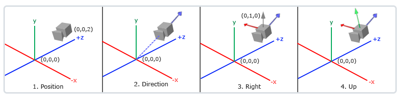
Define a camera:
The location of the camera
The position of the camera is simply a vector pointing to the position of the camera in world space
glm::vec3 P = glm::vec3(0.0f, 0.0f, 3.0f);
B. The direction of the camera
In which direction the camera is pointing, since the camera is pointing in the negative direction of the axis, we want the direction vector to point in the positive direction of the z-axis of the camera. If we exchange the order of subtraction, we will get a vector pointing in the positive z-axis direction of the camera:
glm::vec3 cameraTarget = glm::vec3(0.0f, 0.0f, 0.0f);
glm::vec3 D= glm::normalize(cameraPos - cameraTarget);
C. right axis
Another vector we need is aRight vector(Right Vector), which represents the positive direction of the x-axis of the camera space. In order to obtain the right vector, we need to use a trick: first define aUp vector(Up Vector). Next, cross-multiply the upper vector and the direction vector obtained in the second step. The result of the cross-multiplication of the two vectors will be perpendicular to the two vectors at the same time, so we will get the vector pointing in the positive direction of the x-axis (if we exchange the order of the cross-multiplication of the two vectors, we will get the opposite vector pointing in the negative direction of the x-axis) :
glm::vec3 up = glm::vec3(0.0f, 1.0f, 0.0f);
glm::vec3 R = glm::normalize(glm::cross(up, cameraDirection));
D. upper shaft
Use the right axis and the direction of the camera to cross-multiply to obtain a vector pointing to the camera y-axis.
glm::vec3 U = glm::cross(cameraDirection, cameraRight);
Use the camera's 3 mutually perpendicular axes to define a coordinate space. You can use these three axes plus a translation vector to create a matrix, and you can use this matrix to propose any vector to transform it into that coordinate space. This is what LookAt matrix does of.
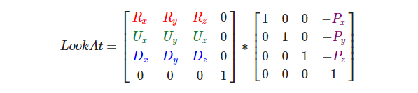
Where R is the right vector, U is the up vector, and D is the direction vector P is the camera position vector. Note that the position vector is the opposite, because we ultimately want to translate the world in the opposite direction to our own movement. Using this LookAt matrix as an observation matrix can efficiently transform all world coordinates into the observation space just defined. The LookAt matrix is as its name implies: it creates an observation matrix that looks at a given target.
Intelligent Recommendation
OpenGL ES coordinate system
OpenGL - Collection - Jianshu.com OpenGLES Learning Road - Coordinate System - Jianshu.com The above article explains the problem of coordinate system. Model view matrix and projection m...
OpenGL coordinate system overview
Foreword In front, we summarize the basic concept of OpenGL. Here we focus on understanding various coordinate systems in OpenGL. First, Cartesian coordinate system Title 2D Cartesian coordinate syste...
OpenGL (7) - coordinate system
MVP transformation M Transformation is a process of converting the coordinates of the object space to the world space coordinates, and can have rotary translational scaling. V Transformation is used t...
OpenGL-coordinate system concept
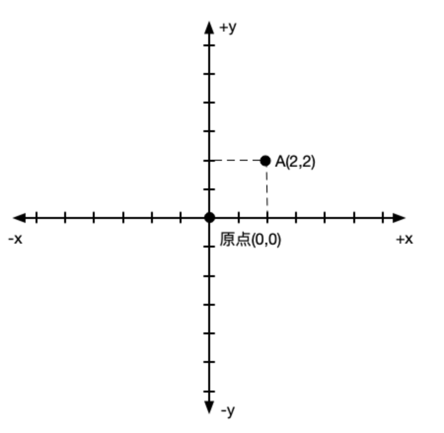
Cartesian coordinate system Two-dimensional drawings:Cartesian coordinates have aX-axisand aY-axiscomposition,X axis is horizontal,Y axis is vertical directionX and Y are perpendicular to each other &...
OpenGL coordinate system introduction
2019 Unicorn Enterprise Heavy Glour Recruitment Python Engineer Standard >>> OpenGL coordinate system introduction OpenGL can be divided into four coordinate systems, namely the world coordin...
More Recommendation
OpenGL coordinate system exercises
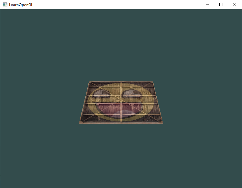
Exercise Let 2D pictures have the following effects: Tilt it slightly to the floor direction. There are some distance from us. There is a perspective effect (the farther the vertex, the smaller it) Re...
OpenGL learning-coordinate system
OpenGL learning-coordinate system Reference for development environment: General configuration steps Visual Studio, create a new empty project Copy the GLAD.C file to your project Select the project, ...
OpenGL coordinate system and unit
1.1 The default coordinate system in OpenGL is the right -handed coordinate system, the default viewpoint position is the origin, the origin is projected at the center of the projection window, and it...

OpenGL ES 3. Coordinate system and coordinate transformation
Hello everyone, next I will introduce OpenGL ES 3. Coordinate system and coordinate transformation. 1. Coordinate system and coordinate space: OpenGL uses a Cartesian right-handed coordinate system. &...
OpenGL Learning Series---Coordinate System
https://glumes.com/post/opengl/opengl-tutorial-coordinate-system/ OpenGL Learning Series---Coordinate System Mental progression of a point coordinate transformation Tue Jan 23, 2018 3700 Words|...