OpenGL Learning Series---Coordinate System
https://glumes.com/post/opengl/opengl-tutorial-coordinate-system/
OpenGL Learning Series---Coordinate System
Mental progression of a point coordinate transformation
Tue Jan 23, 2018
3700 Words|Read in about 8 Min
Tags: OpenGL
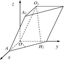
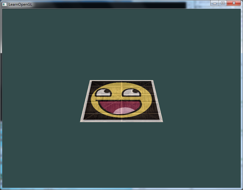
In the basic drawing of the front, I encountered a very obvious problem, the circle is not like a circle, the regular polygon is not like a regular polygon? Just like the following graphic:

A good positive pentagon is sloppy, because our previous drawing is to draw it as a two-dimensional drawing, but in OpenGL it is to draw a three-dimensional one. There is a transition between 2D and 3D, but I have ignored this conversion for the sake of ease of learning. Now I have to understand it.coordinate system!!
coordinate system
Defining the position of a point in the coordinate system of a solid geometry requires the values of the three axes of x, y, and z, and it is also necessary to draw a 3D object in OpenGL.
When drawing the basic shape, only the coordinates of the x and y axes are defined, so the coordinates of the z axis default to 0.
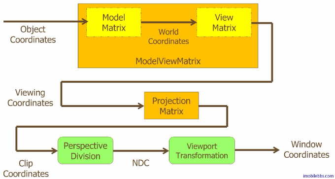
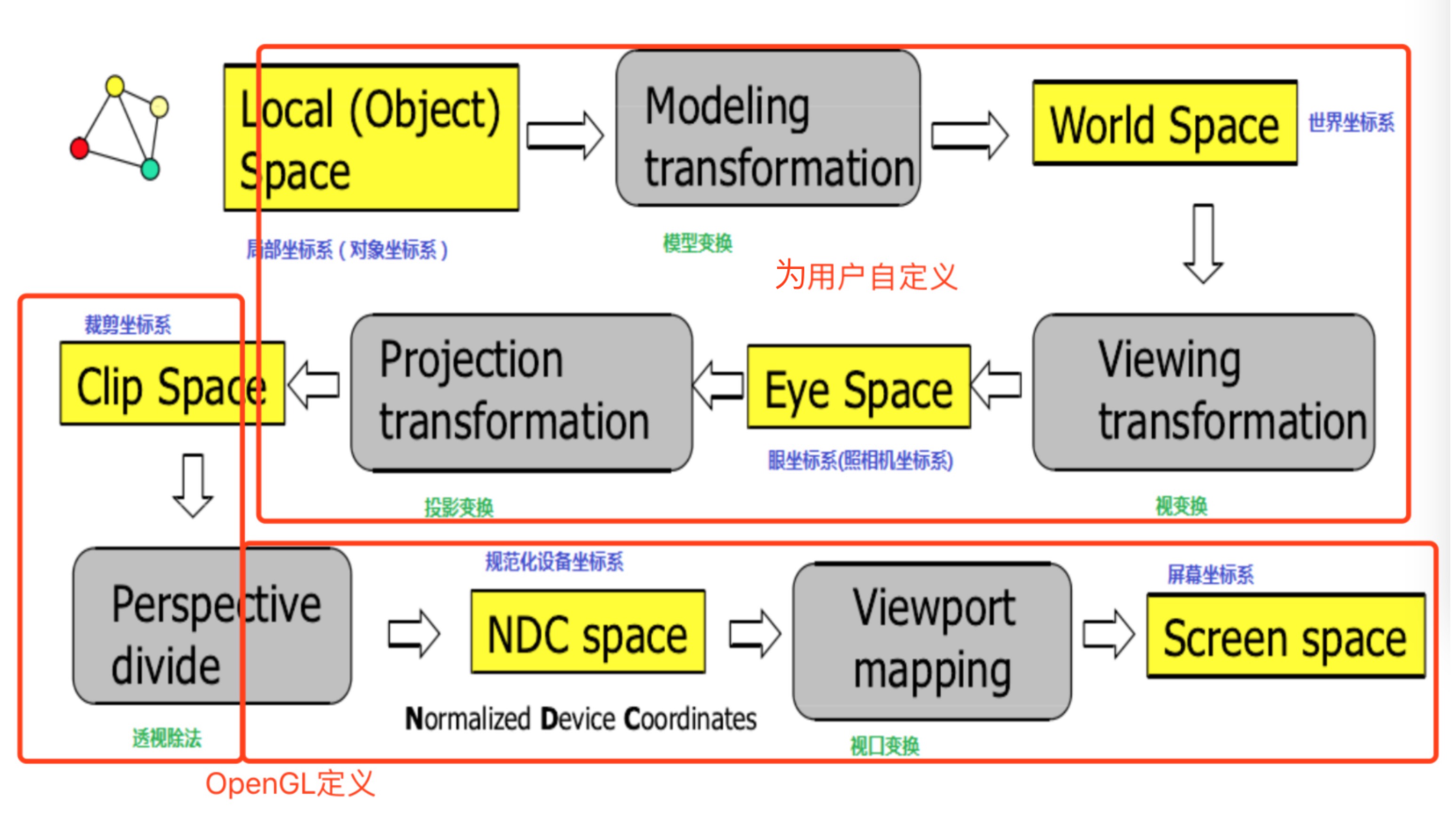
OpenGL converts the values of the defined axes to the actual drawn coordinates, which requires conversion through five coordinate systems.
As shown below:

This involves five coordinate spaces and three transformation matrices:
space:
- Local space
- World Space
- Observation space (View Space)
- Clip Space
- Screen Space
matrix:
- Model Matrix
- View Matrix
- Projection Matrix
According to the flow chart, the conversion of each coordinate space requires a conversion matrix to complete.
The final transformation of the space to the screen space is to map the transformed coordinates to the coordinates of the screen. This process does not require a transformation matrix.
Before entering different coordinate spaces, you need to understand the coordinate system of OpenGL:
OpenGL is a right-handed coordinate system with the positive X-axis on the right-hand side, the positive Y-axis up, and the positive Z-axis through the screen toward you.
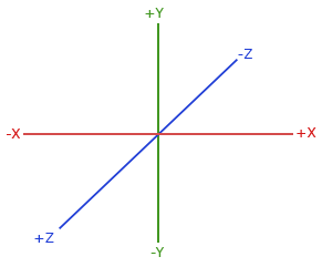
The opposite is the left-handed coordinate system, with the positive Z-axis passing through the screen towards the inside.
Local space
Local space coordinates are the starting point for OpenGL drawing coordinates, and all subsequent conversion operations are performed on the basis of local space coordinates.
The local space coordinates are our own starting coordinate points, which are relative to the origin.(0,0,0)
of.
The space in which it is located is the local space, which means that we define the starting coordinates of the object in the local space.
World space
We define each coordinate point to be in local space, relative to (0,0,0)
of. In this way, when multiple objects are drawn at the same time, they will get together.
World space is a larger coordinate system that is drawn together with all objects, still relative to the origin.
The local space is similar to the world space. You can consider the world coordinate system when defining the coordinate system in the local space, and avoid the phenomenon of pile up when multiple objects are drawn.
Of course, there is a better way to use the Model Matrix.
Using the model matrix, you can shift, scale, and rotate objects.
In this way, the object can be removed from the origin of the coordinate, and some related operations can be performed without considering the definition of the coordinates of the world space in the local space.
Observation space
Looking at the side of the mountain into a peak, the distance is different.
When an object is in place in world space, the next step is to consider which direction and angle to observe the object.
The observation space, which is another OpenGL camera, is the spatial coordinate observed by converting the coordinates of the world space into the perspective of the camera.
That is to say, in the observation space, the coordinate origin is no longer the coordinate origin of the world space, but the camera's perspective is used as the scene origin. This is no longer simply to pan and rotate, but to switch to another In a coordinate system.
OpenGL itself has no concept of a camera, but you can simulate a camera by moving all objects in the scene in opposite directions. This way the scene is not moving and the camera is moving.
To define a camera, or to define a coordinate system whose camera angle is the origin of the coordinates, you need to:
- The position of the camera in world space
- Direction of camera observation
- Pointing to the right side of the camera
- Point to the vector above the camera
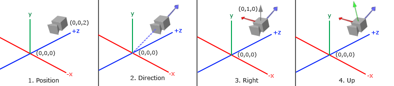
As shown in the figure, a coordinate system with the camera position as the origin is finally established.
Among them, the blue arrow is the Z axis in the camera coordinate system, the green arrow is the Y axis in the camera coordinate system, and the red arrow is the X axis in the camera coordinate system.
The next step is to convert the coordinates of the object in world space to the coordinates of the observation space with the camera angle as the origin.
This also requires a transformation matrix: View Matrix. The coordinate system is switched by the view matrix.
Cutting space
When the object coordinates are all in the observation space, the next thing to do is to crop. Objects within a certain range are cropped according to our needs, and coordinates outside this range are ignored.
The clipping space is essentially a coordinate operation.
From the observation space to the clipping space, you need to use: Projection Matrix.
The projection matrix will specify a range of coordinates, and the coordinates within this range will be converted toNormalized device coordinates , coordinates that are not in this range will be cropped.
The transformation of the coordinates in the observation space after the transformation of the projection matrix is called the projected coordinates, which is also calledCrop coordinates。
It is said that the clipping coordinates are actually to be cropped, and the next clipping process will be done by OpenGL. The transformation of the projection matrix simply filters out the coordinates that do not need to be cropped.
The range created by the projection matrix is a closed spatial geometry calledVision。
The projection matrix has two different forms, and the created view body also has two styles.
Orthogonal projection
Orthographic projection creates a cube-like view. It consists of four directions of left, upper, right and lower directions, and the distance between the near plane and the far plane. The four direction distances define the size of the near and far planes. Coordinate points outside the near and far planes are cropped.
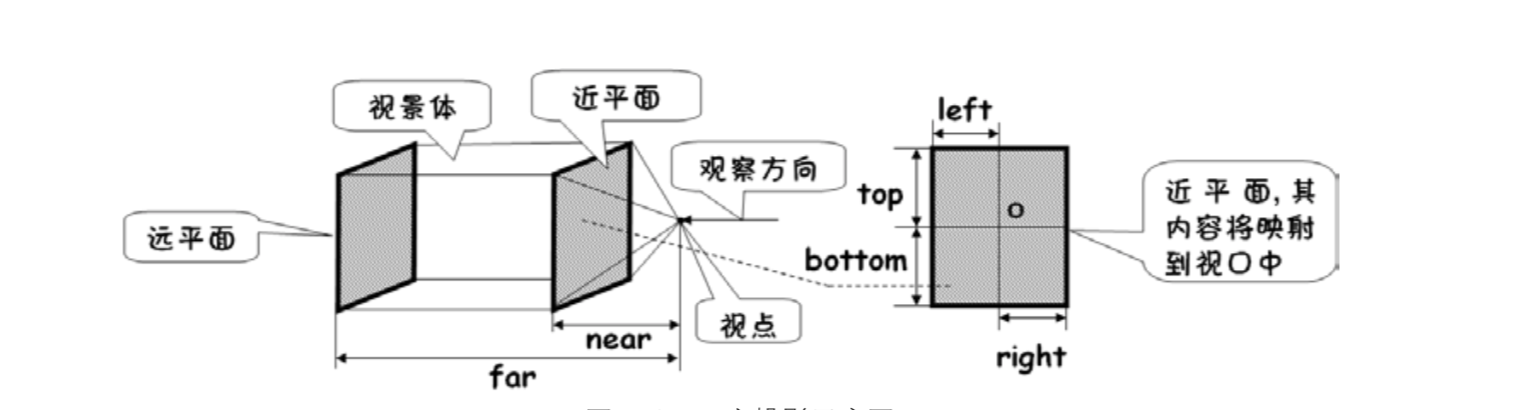
Objects in the scene that are in the scene are projected onto the near plane, and then the projected content on the near plane is mapped onto the screen.
The matrix it uses is an orthogonal projection matrix.
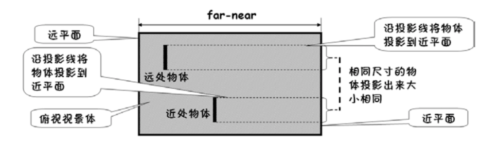
Since orthogonal projection is a kind of parallel projection, its projection lines are parallel, so the graphics projected onto the near plane will not produce real-worldNearly big and smallEffect. Because orthogonal projection does not take perspective into account, objects in the distance do not become smaller, which is suitable for some specific situations.
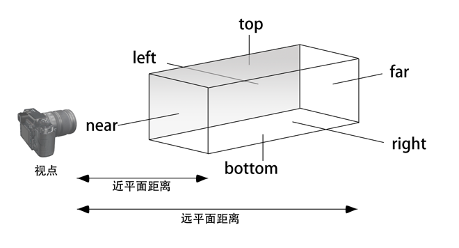
Perspective projection
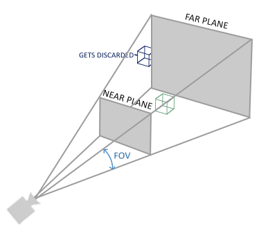
Perspective projection is able to produceNearly big and smallThe effect, like our eyes, looks very small in the distant objects.
The matrix it uses is the perspective projection matrix.
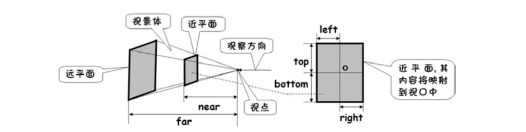
Perspective projection also creates a view body, similar to a cone. It also has near-plane distance and far-plane distance, and it also maps the near-plane content into the screen viewport, but the difference is the same as the orthogonal projection near-plane and far-plane, so its left, upper, right, and lower distances are It is relative to the near plane.

It can be seen that the projection lines of the perspective projection are not parallel to each other and intersect at the viewpoint. Therefore, an object of the same size will have a large projection near the center and a small projection at a distance.
Perspective division
When the coordinates are transformed into the clipping space by the projection matrix, it will be followed.Perspective divisionOperation.
Perspective division is generated in 3D renderingNearly big and smallThe effect is a very important and important step.
Before you go, let’s take a look at OpenGL.w component。
In addition to the x, y, and z coordinates, the OpenGL coordinate system has a w component, which is 1 by default. After the perspective projection transformation, the w component is no longer 1, and the orthogonal projection does not change the w component.
OpenGL is tailored. In essence, the GPU performs the process of cropping. The absolute value of the x, y, and z coordinates is compared with the absolute value of the w component. As long as the absolute value of one component is greater than the absolute value of w, it is considered to be out of view. In the scene, it will be cut off.
After cutting, the perspective division is performed. The x, y, and z coordinates are divided by the w component to obtain new x, y, and z coordinates. Since the absolute values of the x, y, and z coordinates are less than the absolute value of w, the new coordinate values are all located at [−1,1]
Within the interval. The coordinates obtained at this time, that isNormalized device coordinates。
The normalized device coordinates are screen independent and its coordinate system is in the left hand coordinate system.
After the perspective projection matrix transformation, the w components of each coordinate are different, so that after the perspective division operation, the distant objects will appear smaller.
Screen space
With normalized device coordinates, the final step is to project the coordinates onto the screen, which is done by OpenGL.
OpenGL will useglViewPort The function maps the normalized device coordinates to screen coordinates, each of which is associated with a point on the screen. This process is calledViewport transformation. This step no longer requires a transformation matrix.
In this way, the coordinates of a point are completed from the local space coordinates.(x,y,z,w)
To screen coordinates(x,y)
The transformation.
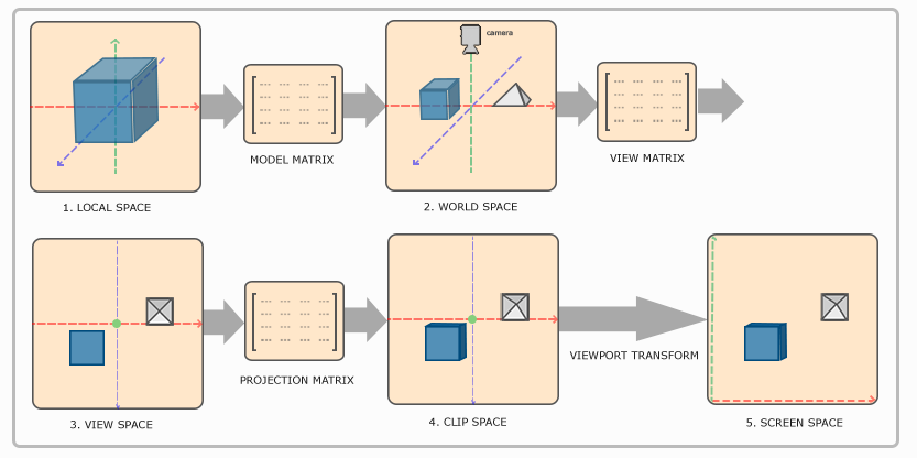
Use a picture to summarize as follows:
Matrix operation of coordinates
The coordinates of the point can be regarded as a vector.V
Representation, and matrixM
Said.
Then, from the local space -> world space -> observation space -> clipping space, the conversion of four spaces, you need to use three transformation matrices,Points need to be left multiplied by a transformation matrix when transforming from one coordinate system to another.The coordinates of the final clipping space can be expressed as follows:
Vclip=Mprojection⋅Mview⋅Mmodel⋅Vlocal
Vclip=Mprojection⋅Mview⋅Mmodel⋅Vlocal
And in the shader script,gl_Position CorrespondingVclip
Crop coordinates.
With the clipping space coordinates, the next thing is to open an OpenGL to complete the cropping and perspective division.
Graphics adapt to aspect ratio
As mentioned at the beginning of the article, the circle drawn becomes an ellipse, and the regular polygons drawn are sloppy, and now the reason can be given.
By default, the coordinate systems of local space, world space, observation space, and clipping space are all coincident, with (0,0,0)
Is the origin of the coordinates. In the beginning, just give the plane coordinate points in the ideal state, and define the shader script as follows:
attribute vec4 a_Position;
void main(){
    gl_Position = a_Position;
}
Then after a series of transformations, the coordinates that OpenGL uses for clipping are still the plane-based coordinates we define, only (x, y)
Value, while the z coordinate defaults to 0 and the w coordinate defaults to 1. The normalized device coordinates after perspective division are still (x, y)
。
The coordinate space assumed by the normalized device coordinates is a square, but the viewport of the phone screen is a rectangle, so that one direction is stretched. The same number of copies, but the longer the length, the greater the length of each one, so it is stretched.
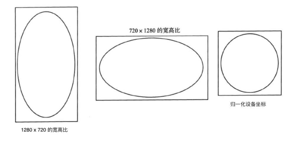
To solve this problem, you can operate on the normalized device coordinates and multiply the longer side by the corresponding scale factor to convert to the same length ratio.
// 1280 * 720 aspect ratio
aspect =  width / height ;
x = x * aspect
y = y
In this way, the ratio of the longer side is enlarged, and the shorter side is taken as the standard of 1.
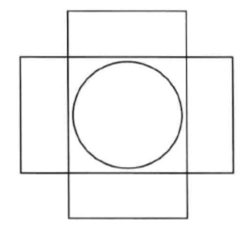
Of course, it is also possible to take into account the stretching before the coordinates are converted to normalized device coordinates, that is, at the time of projection.
When orthogonal projection is used and the width and height of the object are projected onto the near plane, the aspect ratio factor of the screen is taken into account, so that the aspect ratio adaptation of the pattern is completed before conversion to the normalized device coordinates.
In this case, you need to modify the shader scripting language to take the projection matrix into account.
attribute vec4 a_Position;
uniform mat4 u_Matrix;
void main(){
    gl_Position = u_Matrix * a_Position;
}
Specifically, the next blog is written again.
reference
- OpenGL ES Application Development Practice Guide
- OpenGL ES 3.x Game Development
For details on the code, please refer to my Github project:https://github.com/glumes/AndroidOpenGLTutorial
Intelligent Recommendation
openGL coordinate system to another
openGL coordinates including rotation, translation, scaling is tucked inside a matrix. Conversion between the coordinate system is the basis of the operation matrix. Representative of each matrix coor...
OpenGL coordinate system related
Two-dimensional coordinate system 1.1 two-dimensional coordinate system function Three-dimensional coordinate system 2.1-dimensional coordinate system function...
Understanding the coordinate system in OpenGL
Understanding the coordinate system in OpenGL classification The coordinate system in OpenGL is mainly divided into two categories Right hand Left hand as the picture shows Common coordinate system An...
OpenGL--Coordinate system conversion.md
Coordinate System Local Space (Local Space, or Object Space) World Space Observation space (View Space, or Eye Space) Clip Space Screen Space Coordinate system conversion Model matrix View matrix Proj...
OpenGL drawing coordinate system
This project was written in Qt5, using modern OpenGL with a programmable pipeline, implemented by inheriting QOpenGLWidget and QOpenGLExtraFunctions in Qt. It's just the simplest coordinate system. Th...
More Recommendation
Coordinate system in OpenGL
The coordinate system in OpenGL includes model matrix, view matrix, projection matrix From the shader code, we can see that the coordinates of our object vertices are affected by the model matrix, vie...
OpenGL(7) coordinate system
0. Preface In the previous section, we learned about using matrix transformation to transform vertices to achieve that the objects we see are dynamic. But what OpenGL hopes is that every time the vert...
2. OpenGL-coordinate system
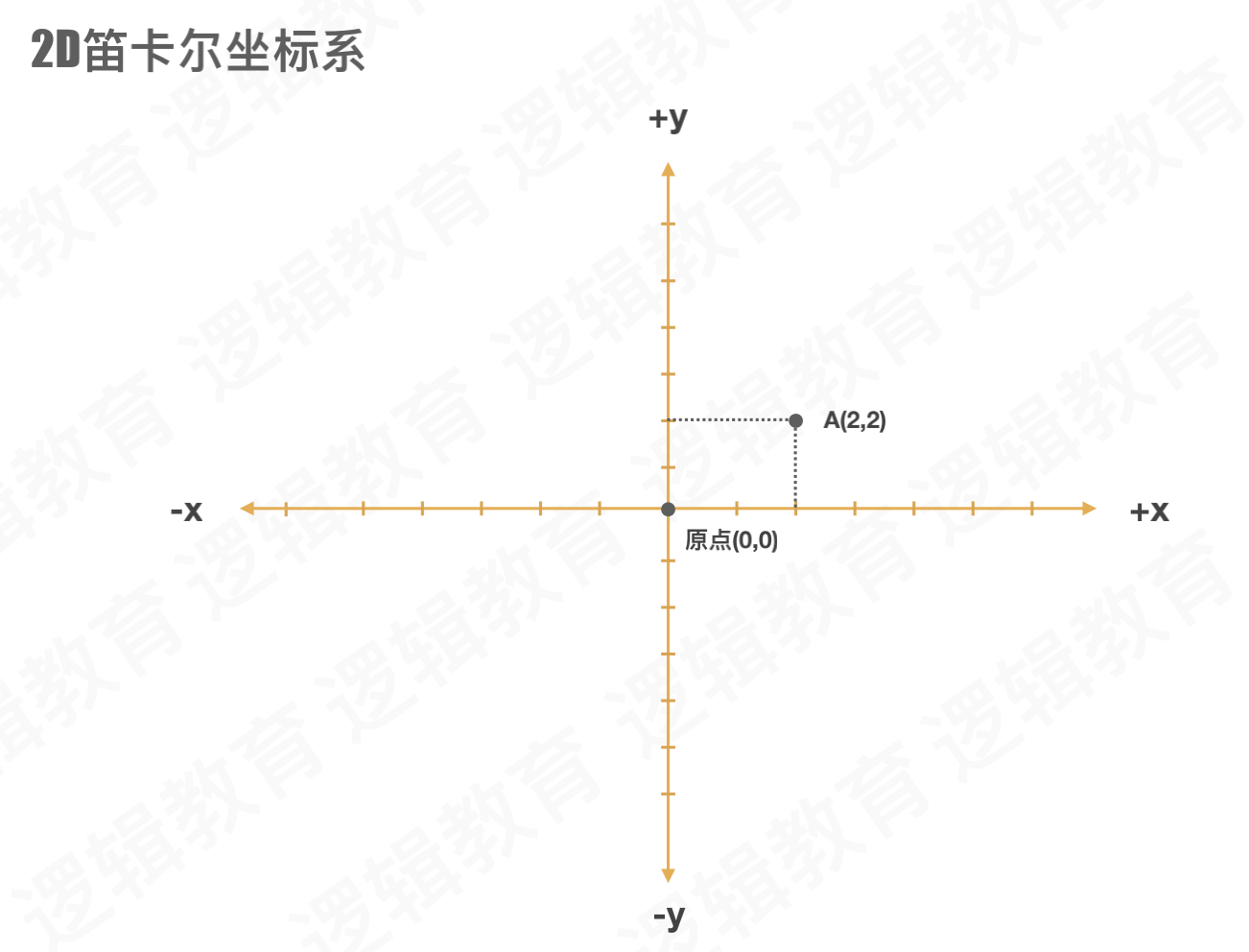
OpenGL-coordinate system 1. Cartesian coordinates 1.1, 2D Cartesian coordinate system Plane coordinate system, only X and Y axis 1.2, 3D Cartesian coordinate system The three-dimensional coordi...
OpenGL--detailed coordinate system
OpenGL-detailed coordinate system The device screen to which OpenGL finally renders graphics is essentially 2D. The process of rendering graphics is the process of converting a 3D scene into a final 2...
The coordinate system of opengl in vs2019
OpenGL hopes that every time the vertex shader runs, all the vertices we can see are Normalized Device Coordinate (NDC). In other words, the x, y, and z coordinates of each vertex should be between -1...