This experience system introduces the various settings of the oscilloscope in the multisim software. There are usages for the advanced settings that are not commonly used in oscilloscopes and four-track oscilloscopes.
How to use multisim oscilloscope and four trace oscilloscope
tags: Multisim Oscilloscope Four Trace Oscilloscope
Method / Step
-
First, bring up the instrument toolbar, right-click on the menu bar, and then select the instrument, so that there is a tick status in front of the instrument, as shown in the figure
-
Then you will find the instrument bar appears on the right side of the work area, as shown in the red frame
-
The first one in the instrument column is a multimeter, the fourth one in turn is the oscilloscope, and the fifth one is the four-track oscilloscope;
First look at the usage of the oscilloscope. The oscilloscope has two channels, which can observe two signals at the same time. For example, if we want to see the voltage change across a resistor, then connect the A channel of the oscilloscope and the two ends of the resistor in parallel, as shown in the figure
-
If you also want to see the voltage changes across the capacitor, then connect the two ends of the capacitor in parallel to the B channel, as shown in the figure
-
When the circuit diagram is very complicated, the signals of each channel may look messy. We can set the color of different signal channels. How to set it? It is set by setting the color of the wire connected to the oscilloscope, for example, select the wire connected to the positive pole of the B channel of the oscilloscope, right-click, and then select the color segment, select a desired color, as shown in the figure
-
After setting, we start to simulate the observation signal, double-click on the oscilloscope you placed to open the display panel, and then turn on the simulation switch, as shown in the figure
-
Since the scale has not been set, the signal display effect may be inappropriate as shown in the figure
Below the signal display window are the relevant settings of the time axis, channel A and channel B. Adjust the time axis ratio, channel A ratio, and channel B ratio to enlarge or reduce the time and signal amplitude; the channel ratio is below Select the switch, if you want to observe the AC signal, you need to choose AC, you need to look at the DC signal, choose DC, if you do n’t want to see the signal of the channel, then choose 0, there is an inverting switch below the B channel, which is the opposite of the original value, adjust The result is as shown below
-
-
The previous experience introduced the usage of the oscilloscope. This article will introduce the usage of the four-track oscilloscope and explain the advanced settings of the oscilloscope in detail.
-
The fourth trace oscilloscope is the fifth in the instrument toolbar, as shown in the figure,
-
The so-called four-track oscilloscope has 4 channels, ABCD, as shown in the circuit in the figure, if you want to observe the four signals of resistance R1, resistance R2, capacitor C1, and inductance L1, then connect them to the corresponding channels respectively. The color setting method has been I will not repeat them here in the previous experience introduction; finally, the G terminal of the four-track oscilloscope should be connected to the ground, as shown in the figure
-
Now look at the simulation results, which is slightly different from the setting method of the oscilloscope. The four-track oscilloscope selects the corresponding channel by selecting the middle disk as shown in the red frame on the left, and then sets the channel ratio. Adjust to the appropriate display result as shown in the right figure. Note that the observed signal is only the voltage value of the connection terminal, and does not necessarily represent the voltage across the device. For example, the signals of the C and D channels connected to L1 and C1 in the figure only represent the voltage at one end. Voltage.
-
The signals observed above are all internal triggers. The default is A channel trigger, you can set other channels; click A> in the lower right corner and then select one of A B C D channels, as shown in the figure
-
What does the oscilloscope have another T channel for? This is used to connect the external trigger signal in the external trigger mode. First, select external in the trigger setting, as shown in the left figure, and then connect the trigger signal to the T channel as shown in the right figure;
END
-
The oscilloscope is essentially the voltage difference between the two ends of each channel; the four-track oscilloscope is essentially the voltage difference between each channel and the G terminal
Intelligent Recommendation

Multisim Basics - Change the color oscilloscope different ports
When the oscilloscope screen display multiple signals simultaneously, often no way to identify dazzling, see which signal is which Change the color of different ports, you can easily distinguish each ...
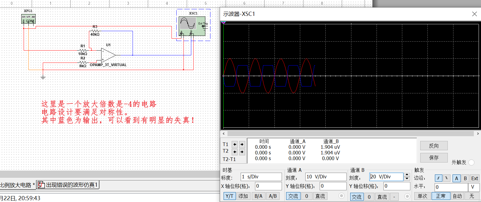
A solution to the problem of oscilloscope display signal distortion in multisim
Multisim simulation op amp inverse proportional amplifier circuit: I wanted to use simulation to build a waveform generator, but I tried several kinds of them to no avail, so I had to study the basic ...
Note - Learning [Zi Chuang] How to use oscilloscope
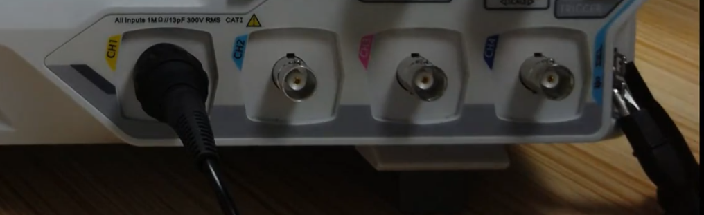
Measure a waveform Oscilloscope probe Insert the oscilloscope into the CH channel, the hook on the probe wants to stand the signal to be tested, and the crocodile clip has to clamp the signal to be te...
How to debug waveform with oscilloscope
sequence Whether you are an embedded hardware engineer or an embedded software engineer, the use of oscilloscopes can be regarded as a necessary skill, because we encountered some problems when we wer...
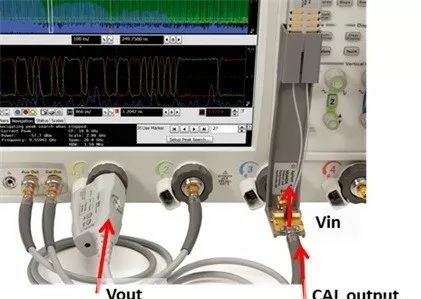
How to calibrate the oscilloscope probe
An oscilloscope is a common electronic device in electronic testing equipment. It is used by electronic engineers to measure the signal output of the relevant circuit and the corresponding voltage and...
More Recommendation

Note the use of an oscilloscope
Forwarded from this tutorial, speak very good Oscilloscope Tutorial 1. Scope Waveform to see how In fact, you only need to learn how to use the oscilloscope most frequently usedSeveral key knobYou wil...
How to use the oscilloscope fishes? 90% of engineers will ignore these details ...
2018-04-17 Electronics Engineer Electronic Engineering Times Editor: Electronic Engineering Times I believe the power engineer, oscilloscope credit is irreplaceable, once the product in question will ...
Have you used an oscilloscope? Graphic and text teach you how to use it!
Have you used an oscilloscope? Graphic and text teach you how to use it! The full name of the oscilloscope is a cathode ray oscilloscope. It is an electronic instrument for observing and measuring ele...
Note - Learning [Zi Chuang] How to use oscilloscope -Cursor
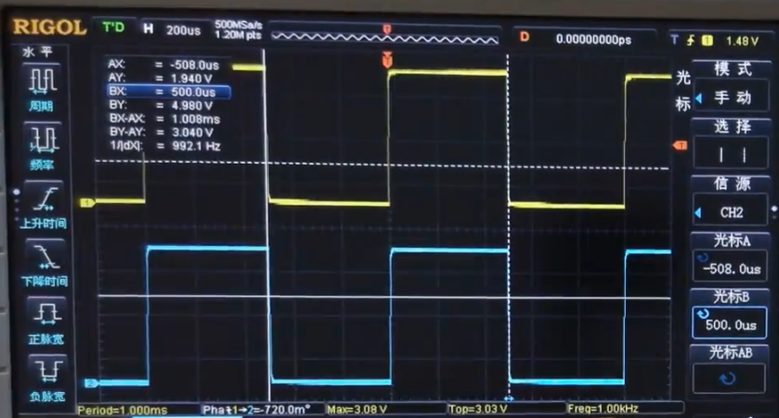
Cursor effect When we observe the information of a signal, we can observe the automatic measurement of the oscilloscope. Such as follows: But when we want to analyze a duty cycle or frequency of a wav...
Note - Learn [Zijian] How to use oscilloscope - Thabary Flat Covers
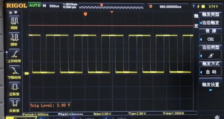
Touch fast effect By adjusting the trigger level, a constantly running wave type is stabilized. use Adjust the trunk electric flat knob, which will display an orange line on the screen, as shown: The ...