An easy-to-use isolated 4-20mA generating circuit
In the circuit design, 4-20mA generating circuit is commonly used. There are many design schemes on the Internet, and of course there are ready-made chips (such as AD694, which I have used before, and these chips are generally compared). Regardless of whether it is a circuit or a chip, most of them are not isolated from the MCU, and at the same time, there are also no isolation between several 4-20mA circuits. This kind of stability on the industrial site is easily affected.
By analyzing other people's isolation card circuits, a better and less expensive design is obtained.
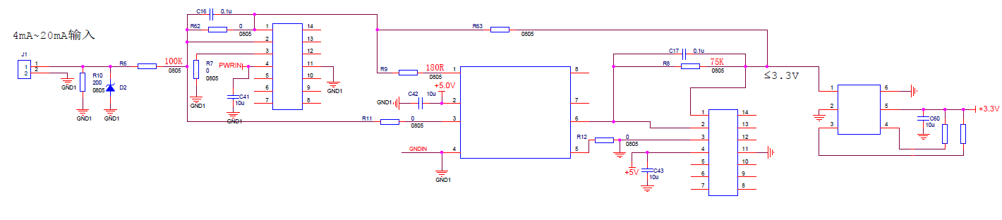
The core circuit is as follows:
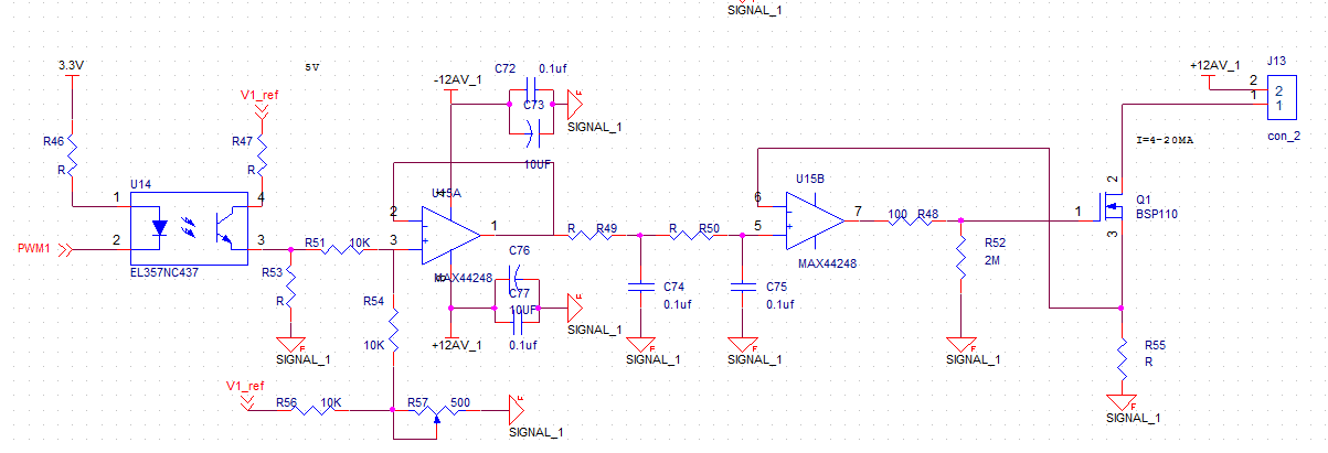
The left side of the optocoupler is isolated from the right side. The left side is generally controlled by a microcontroller, CPLD, DSP, etc., V_ref on the 4th pin of the optocoupler is a 5V reference source (such as TL431), and the voltage of the 3rd pin of the op amp is determined by the 3rd pin of the optocoupler The output PWM and the adjustable resistor R57 are composed of two parts. The following two sets of RC low-pass filtering get the DC voltage, divided by R55 is the output current.
The circuit has several points:
1. This part of the adjustable resistor R57 is mainly used to improve the benchmark. For example, the original current output is at least 0mA, which can be increased to about 4mA, which simplifies the output accuracy.
2. Each group of 4-20mA circuits are isolated, but the two grounds between adjacent 4-20mA circuits need to be connected to a varistor. If they are not connected, they will interfere with each other, and I do n’t have specific reasons. Clearly, I discovered it during the original test. If you know the reason, hope to inform.
3. Isolation of power supply can be directly purchased off-the-shelf DCDC isolation chip, 1W is enough, I used Jinshengyang A2412S-1WR2, it seems to be more than a dozen pieces, if you consider the cost you can use a transformer, while outputting multi-channel isolated power, I am on the transformer The design is unfamiliar, so I won't talk about it here.
Intelligent Recommendation
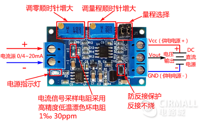
4~20ma current to voltage
■With anti-reverse power connection function, the module will not be burned when the power supply is reversed. Basically, Taobao similar products do not have this function. ■Zero point and range can b...

Hardware notes: 4~20mA input/0~5V output I/V conversion circuit
========================================================================================================================== V14=(8+2)*2.5/8=-3.125V, v17=0.1*(-3.125V)/(3.01+0.1); v14=-3.125,v17=...
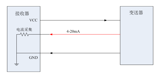
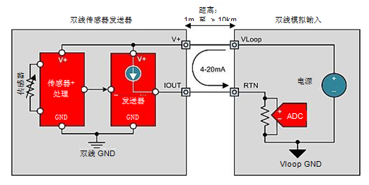
Introduction to 4-20mA current loop transmission circuit of 2-wire system and 3-wire system
1) Why use 4-20mA current loop In long-distance and complex industrial sites, it is often necessary to collect signals from long-distance distances. Usually, several issues need to be considered: Firs...
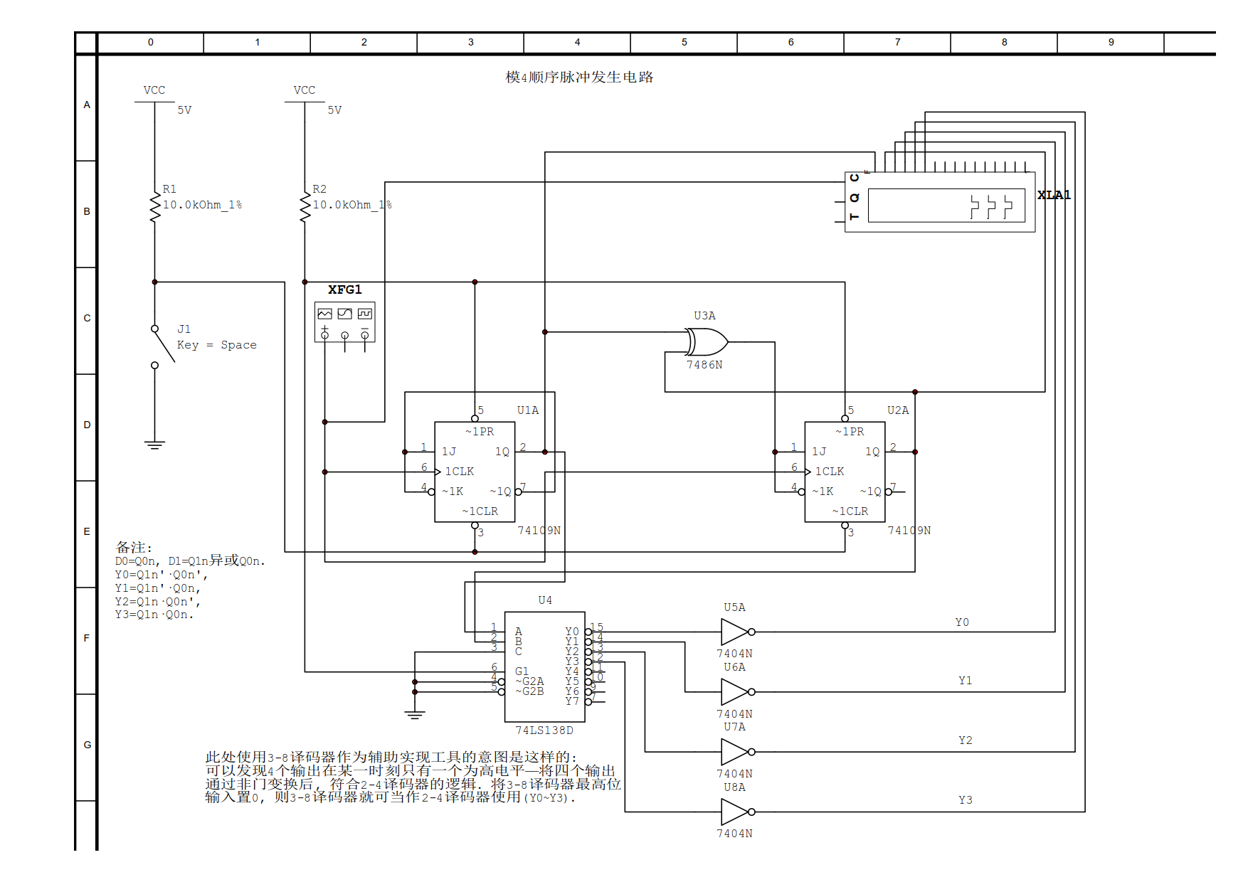
Design of modulo 4 sequential pulse generating circuit
(1) State table of column 4 sequential pulse generating circuit: (2) Select the D trigger and draw the state excitation table according to the state table: (3) Find the state excitation equation, subs...

4~20mA turn 0~5V
The RCV420 is a precision I/V converter circuit and is currently the best 4-20mA conversion 0-5V circuit solution available in commercial grades (0°C-70°C) and industrial grades (-25°C-+85...
More Recommendation
4-20mA signal acquisition (1)
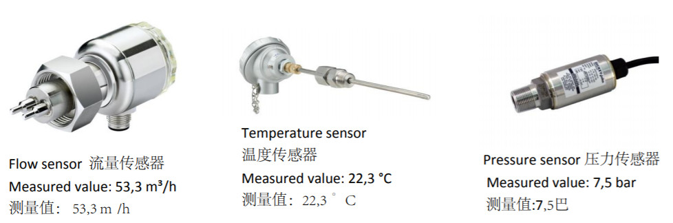
4-20mA basic knowledge Some analog quantities need to be collected on industrial pipelines, such as temperature, pressure, humidity, flow rate, etc. The physical quantities of these non-electrical sig...
Summary of 4~20ma current control
When the acquisition chip uses 1110, please note that the range range is ±2.08V, which is different from 1100±3.3, or it may result in a full output. At this time, the R10 resistance sho...
[Isolated code (4)] use "breeding" memory function fit curve
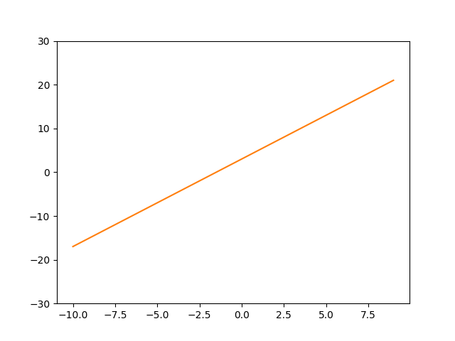
skills requirement: Through these two days of writing programs to fit a function curve; Draw the fitted curve; Complete code: Demonstration: Experience: If you print a line diagram with a PLOT functio...
4-20mA current loop transmitter entry (turn)
Getting Started with 4-20mA Current Loop Transmitter Author:Collin Wells, Texas Instruments Precision Analog Application Engineer In modern industrial control systems, the 4-20 mA current loop tr...
Why a 4 ~ 20mA current to transmit analog?
This switched Thank the author, there are two reasons to send this microblogging: 1 to prepare his later work, if spend it! 2. It should be a good article to share with you. We would never do with any...