Detailed explanation of STM32 standard peripheral version USB driver library (architecture + file + function + instruction + sample program)
Write in front
- Currently, there are two sets of ST USB drivers, one of which is an early independent version of the USB driver, which is called in the official training documentLegacy library, The latest version is 2.2.0; a set of drivers for its Cube series, which may be different depending on the chip, see the Cube driver package of the corresponding chip for details, which is called in the official training documentCube library. This article uses the Legacy libraryUSB driver. For more details, please refer to the blog postSTM32 USB IP (USB module) detailed。
- This article is mostly derived from ST official documents and training documents from 2016 to 2017. Readers can also go directly to the ST official website to check related documents.
- Slightly involvedUSB 2.0 specificationThe contents of the USB specification goOfficial websiteOr Google it yourself. You can also refer to:
- Detailed Explanation of USB 2.0 Specification Part One
- Detailed Explanation of USB 2.0 Specification of USB Part 2
About the drive
STM32 MCU has two IPs with USB function

There are different independent versions of drivers for different chips (mainly chips are different, and USB is different). There are currently the following:
- STSW-STM32046: Mainly for STM32F105/7, STM32F2 and STM32F4 USB on-the-go Host and device library, the corresponding documentation is UM1021. The download address ishttps://www.st.com/content/st_com/en/products/embedded-software/mcus-embedded-software/stm32-embedded-software/stm32-standard-peripheral-library-expansion/stsw-stm32046.html, The latest version of the driver for this version is 2.2.0. The following is an example of this driver.
- STSW-STM32121: Mainly for STM32F10x, STM32L1xx and STM32F3xx USB full speed device library, the corresponding documentation is UM0424.
The download address ishttps://www.st.com/content/st_com/en/products/embedded-software/mcus-embedded-software/stm32-embedded-software/stm32-standard-peripheral-library-expansion/stsw-stm32121.html, The latest version of the driver for this version is 4.0.1. - STSW-STM32092: Mainly for STM32F0x2xx USB FS device library, the corresponding description is UM1717. The download address ishttps://www.st.com/content/st_com/en/products/embedded-software/mcus-embedded-software/stm32-embedded-software/stm32-standard-peripheral-library-expansion/stsw-stm32092.html, The latest version of this driver is 1.0.0. It should be noted here that this driver is for STM32F0x2xx, but it can be easily transplanted to STM32F0xx series MCUs. It should be noted that the driver needs to be modified according to the clock of the specific chip.
usb_conf.hwithusb_bsp.c. For specific transplantation, please refer to this article by netizensUSB library STM32F0x2 ported to STM32F070 notes
The following articles mainly introduceSTSW-STM32046. About STM32 USB IP, please refer to the blog post for more detailsSTM32 USB IP (USB module) detailed
Drive structure
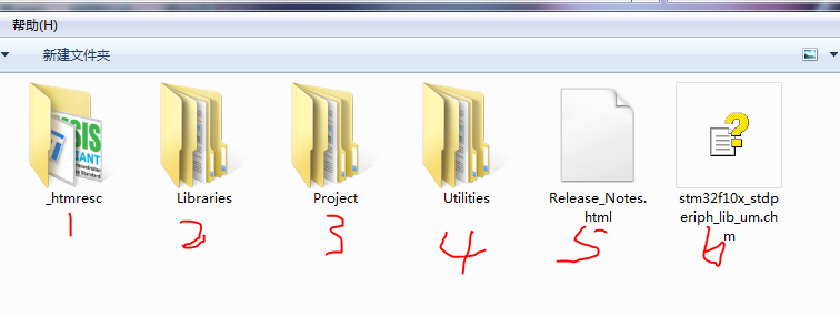
Currently, the standalone USB driver does not support all STM3 chips.And ST no longer maintains the independent version of the USB library (replaced by the Cube series), See the driver source code for details. The structure of the driver source code is relatively simple, mainly includingDriver library source code, usage examples, other utilities, release notesFour major parts. The drive directory structure is shown below:

The focus is on the Libraries directory. The USB OTG is the basis of USB Device and USB Host.In actual use, USB OTG is the underlying driver of USB Device and USB Host. (In the beginning, I thought that each part could be used independently!!).
In addition, you can see from the figure above that the USB library also contains the source code of the standard peripheral library. Mainly because there was no HAL library before. And in the Cube series, ST has re-implemented all the source code (including the USB driver), namely the HAL library.But it should be noted that the above USB library can not only be used with the standard peripheral library, but also with the HAL library.
This article mainly describes the USB driver, the standard library driver in the same directory (detailed descriptions in other blog posts) will not be discussed. Other parts can be used as references in the actual transplantation process, such as various sample programs, etc., and will not be introduced in detail. The structure of the entire driver library of the USB driver is as follows:

USB OTG core
USB OTG core,Namely: USB OTG controller embedded in STM32 chip. STM32F105/07xx devices have embedded a USB OTG FS kernel, while STM32F2xx and STM32F4xx devices have embedded a USB OTG FS kernel and an HS kernel. See below:

compare as follows:

USB chip is also divided into Controller part and PHY part. The Controller part mainly implements the USB protocol and control. The internal logic mainly includes the MAC layer, CSR layer and FIFO control layer, as well as other low-power management levels. MAC implements data packet packing and unpacking according to the USB protocol, and sends the data to the PHY according to the UTMI bus format (USB3.0 is PIPE). The CSR layer performs register control. The software controls the USB chip through the CSR register. This part is interactively accessed with the CPU, mainly as a Slave through AXI or AHB. The FIFO control layer mainly interacts with DDR and controls the channel through which USB transfers data from DDR. It is mainly used as a Master to interact through AXI/AHB. The PHY part of the function mainly realizes the function of parallel-to-serial conversion, converting the parallel data of the UTMI or PIPE port into serial data, and then outputting to the outside of the chip through the differential data line.
Generally speaking, if the usb phy is packaged in the chip, the UTMI+ interface is basically used. The ULPI interface is generally used if it is not packaged into the chip, which can reduce the number of pins.
For the OTG FS controller, OTG HS controller, and OTG FS PHY embedded in the STM32 chip, please refer to the chip manual.
From a netizenUSB's phy protocol development history
USB OTG full speed core
OTG_FS is a dual-role device (DRD) controller that supports slave and host functions at the same time, and fully complies with the On-The-Go supplementary standard of the USB 2.0 specification. In addition, the controller can also be configured in "host only" mode or "slave only" mode, fully compliant with USB 2.0 specifications. In master mode, OTG_FS supports full-speed (FS, 12 Mb/s) and low-speed (LS, 1.5 Mb/s) transceivers, while in slave mode, it only supports full-speed (FS, 12 Mb/s) transceivers. OTG_FS supports both HNP and SRP. The only external device required in host mode is a charge pump that provides VBUS. The hardware block diagram is as follows
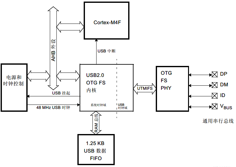
OTG_FS supports HNP (Host Negotiation Protocol) and SRP (Session Request Protocol). The only external device required is the charge pump of the VBUS power supply in Host mode.
The general characteristics of the OTG_FS interface are as follows:
- Certified by USB-IF, compliant with Universal Serial Bus Specification Version 2.0
- The embedded PHY of the module also fully supports the OTG protocol defined in the standard specification OTG Supplement 1.3
- Support A-B device identification (ID line)
- Support Host Negotiation Protocol (HNP) and Session Request Protocol (SRP)
- Allow the host to turn off VBUS to save battery power in OTG applications
- Support monitoring of VBUS level through internal comparator
- Support dynamic switching of roles from master to slave
- The following roles can be configured through software:
- USB FS slave with SRP function (B device)
- USB FS/LS host with SRP function (A device)
- USB On-The-Go Full Speed Dual Role Device
- Support FS SOF and LS Keep-alive tokens
- SOF pulse can be output via PAD
- SOF pulse is internally connected to Timer 2 (TIM2)
- Configurable frame period
- Configurable end-of-frame interrupt
- With power saving functions, such as stopping the system during USB suspension, turning off the digital module clock, and managing the power of PHY and DFIFO
- 1.25 KB dedicated RAM with advanced FIFO control
- The RAM space can be divided into different FIFOs for flexible and effective use of RAM
- Each FIFO can store multiple data packets
- Dynamically allocate storage
- The FIFO size can be configured to a value other than a power of 2 for continuous use of memory cells
- No need for application intervention within one frame to achieve the maximum USB bandwidth
The OTG_FS interface has the following main features and requirements in host mode:
- The VBUS voltage is generated by an external charge pump.
- Up to 8 host channels (pipes): Each channel can be dynamically reconfigured to support any type of USB transmission.
- The built-in hardware scheduler can:
- Store up to 8 interrupts plus synchronous transmission requests in the periodic hardware queue
- Store up to 8 control plus bulk transfer requests in aperiodic hardware queue
- Manage a shared RX FIFO, a periodic TX FIFO and a non-periodic TX FIFO to effectively use the USB data RAM.
The OTG_FS interface has the following characteristics in slave mode:
- 1 bidirectional control endpoint 0
- 3 IN endpoints (EP), configurable to support bulk transfer, interrupt transfer or synchronous transfer
- 3 OUT endpoints, configurable to support batch transmission, interrupt transmission or synchronous transmission
- Manage a shared Rx FIFO and a Tx-OUT FIFO to efficiently use USB data RAM
- Manage up to 4 dedicated Tx-IN FIFOs (one for each enabled IN EP) to reduce application load
- Support soft disconnect function.
For a detailed description of this part, see section 34 of the chip's reference manual: USB on-the-go full-speed (OTG_FS)
USB OTG high speed core
OTG_HS is a dual-role device (DRD) controller that supports both slave and host functions, and fully complies with the On-The-Go supplementary standard of the USB 2.0 specification. In addition, the controller can also be configured as a master-only or slave-only controller, which is fully compliant with USB 2.0 specifications. In master mode, OTG_HS supports high-speed (HS, 480 Mbits/s), full-speed (FS, 12 Mbits/s) and low-speed (LS, 1.5 Mbits/s) transmission, while in slave mode, only high-speed (HS , 480 Mbits/s) and full speed (FS, 12 Mbits/s) transmission. OTG_HS also supports HNP and SRP. The only external device required in OTG mode is a charge pump that provides VBUS.

USB DMA does not support internal Flash addressing
OTG_HS supports HNP (Host Negotiation Protocol) and SRP (Session Request Protocol). The only external device required is the charge pump for the VBUS power supply in OTG mode.
The general characteristics of the OTG_HS interface are as follows:
- Certified by USB-IF, in line with Universal Serial Bus Specification Version 2.0
- Support 3 PHY interfaces
- On-chip full speed PHY
- I2C interface for connecting external full-speed PHY
- ULPI interface for external high-speed PHY
- Support Host Negotiation Protocol (HNP) and Session Request Protocol (SRP)
- Allow the host to turn off VBUS in OTG applications to save power consumption without the need for external components
- Allows use of internal comparator to monitor VBUS level
- Support dynamic role switching between master and slave
- The following roles can be configured through software:
- USB HS/FS slave supporting SRP (B device)
- USB HS/FS/LS host supporting SRP (A device)
- USB OTG FS dual role device
- Support HS/FS SOF and low-speed (LS) "Keep-alive" tokens and have the following functions:
- SOF pulse pin output function
- Internal connection between SOF pulse and timer 2 (TIM2)
- Configurable frame period
- Configurable end-of-frame interrupt
- The module is embedded with DMA, and the burst transfer type of AHB can be configured by software
- Possess power-saving functions, such as stopping the system clock during USB suspend, turning off the internal clock domain, PHY and DFIFO power management of the digital module
- Dedicated 4K bytes data RAM with advanced FIFO management:
- The storage area can be configured as different FIFOs for flexible and efficient use of RAM
- Each FIFO can contain multiple data packets
- Dynamic memory allocation
- The FIFO size can be configured to a value other than a power of 2 for continuous use of the storage area
- No need for application intervention within one frame to achieve the maximum USB bandwidth
The characteristics of the OTG_HS interface in host mode are as follows:
- Requires external charge pump to generate VBUS
- With up to 12 host channels (pipes), each channel can be dynamically reconfigured to support any type of USB transfer
- Built-in hardware scheduler:
- Store up to 8 interrupts plus synchronous transmission requests in the periodic hardware queue
- Store up to 8 control plus bulk transfer requests in aperiodic hardware queue
- Manage a shared RX FIFO, a periodic TX FIFO and a non-periodic TX FIFO to effectively use the USB data RAM
- In the host mode, it has the function of dynamically adjusting the SOF frame period
The OTG_HS interface has the following characteristics in slave mode:
- Has 1 two-way control endpoint 0
- With 5 IN endpoints (EP), which can be configured to support bulk, interrupt or synchronous transmission
- With 5 OUT endpoints, which can be configured to support bulk, interrupt or synchronous transmission
- Manage a shared Rx FIFO and a Tx-OUT FIFO, which can efficiently use USB data RAM
- Manage up to 6 dedicated Tx-IN FIFOs (one for each EP configured in IN) to reduce application load
- With soft disconnect function
For a detailed description of this part, see section 35 of the chip's reference manual: USB on-the-go high-speed (OTG_HS)
USB OTG low level driver files
USB OTG driver source code directory structure and code structure are shown below:

| Module | file | Description |
|---|---|---|
| Common | usb_core.c/h | This file contains hardware abstraction layer and USB communication operations |
| Common | usb_conf_template.h | This file contains the core configuration parameters of the host, device and OTG mode: send FIFO size, receive FIFO size, core mode and selected functions, etc.*Users need to use this file to configure the USB OTG low level driver reasonably according to their needs. This file should be copied to the application folder and modified according to the needs of the application. |
| Common | usb_bsp_template.c | This file contains the low-level core configuration (interrupt, GPIO, etc.) used by USB.The user needs to use this file to configure the hardware resources used by the USB. This file should be copied to the application folder and modified according to the needs of the application. |
| Host | usb_hcd.c/h | The file containsUSB_HOST_LibraryHost interface layer used when accessing the core. |
| Host | usb_hcd_int.c/h | This file contains interrupt subroutines used in Host mode. |
| Device | usb_dcd.c/h | The file containsUSB_HOST_DEviceThe Device interface layer used to access the core. |
| Device | usb_dcd_int.c/h | This file contains interrupt subroutines in Device mode. |
| OTG | usb_otg.c/h | This file contains the implementation of SRP and HNP protocols and interrupts about OTG mode. |
USB OTG low level driver configuration
USB OTG low level driver configuration is through ausb_conf.hThe configuration file is configured. In the actual migration process, you can copy the source codeusb_conf_template.hThen renamedusb_conf.h, Then edit and modify. The specific configurable items are shown in the following table:
| definition | description |
|---|---|
| USB_OTG_FS_CORE | Enable the full speed mode of the core |
| USB_OTG_HS_CORE | Enable the high-speed mode of the core |
| RX_FIFO_FS_SIZE | Set the size of the received FIFO in full speed mode |
| RX_FIFO_HS_SIZE | Set the size of the received FIFO in high-speed mode |
| TXn_FIFO_FS_SIZE | Set the size of the send FIFO of the specified device endpoint in full speed mode, n is the index value used by the endpoint number of the device |
| TXn_FIFO_HS_SIZE | Set the size of the sending FIFO of the specified device endpoint in high-speed mode, n is the index value used by the endpoint number of the device |
| TXH_NP_FS_FIFOSIZ | Set the size of the FIFO sent aperiodically when used as a USB Host in full-speed mode |
| TXH_NP_HS_FIFOSIZ | Set the size of the non-periodically sent FIFO in high-speed mode as a USB Host |
| TXH_P_FS_FIFOSIZ | Set the size of the FIFO sent periodically when used as a USB Host in full-speed mode |
| TXH_P_HS_FIFOSIZ | Set the size of the FIFO periodically sent when used as a USB Host in high-speed mode |
| USB_OTG_ULPI_PHY_ENABLED | Enable the PHY of the ULPI interface for high-speed mode.Usually an external PHY chip |
| USB_OTG_EMBEDDED_PHY_ENABLED | FS PHY embedded in the high-speed mode chip.Generally, a PHY chip is embedded in the STM32 series chips. Different chips have different PHY support for full speed and high speed. |
| USB_OTG_HS_LOW_PWR_MGMT_SUPPORT | Enable low-power management function in high-speed mode |
| USB_OTG_FS_LOW_PWR_MGMT_SUPPORT | Enable low power management function in full speed mode |
| USB_OTG_HS_INTERNAL_DMA_ENABLED | Enable DMA feature in high-speed mode |
| USB_OTG_HS_DEDICATED_EP1_ENABLED | When the high-speed mode is enabled, as a USB Device, the characteristics of the dedicated endpoint 1 |
USB OTG low level driver use
In the use of USB OTG low level driver, the configuration options areusb_conf.hin. In addition, for the definition of certain variables, there are also the following matters needing attention.
The Rx and Tx FIFOs size and start address are set inside this function to use one more endpoints in addition to the control Endpoint (0). The user can change the FIFO settings by modifying the default values and changing the FIFO depth for each Tx FIFO in the usb_conf.h file.
Low level driver structures
This part uses a structureUSB_OTG_CORE_HANDLETo define the variables, states and buffers that need to be used. This structure is also the first structure that users need to pay attention to when using. details as follows:
typedef struct USB_OTG_handle
{
  USB_OTG_CORE_CFGS    cfg;
  USB_OTG_CORE_REGS    regs;
#ifdef USE_DEVICE_MODE
  DCD_DEV     dev;
#endif
#ifdef USE_HOST_MODE
  HCD_DEV     host;
#endif
#ifdef USE_OTG_MODE
  OTG_DEV     otg;
#endif
}
USB_OTG_CORE_HANDLE , *PUSB_OTG_CORE_HANDLE;
At the same time when using DMA, you need to pay attention to:
- Currently, DMA is only used in high-speed mode.
- When using DMA, it is necessary to ensure that all structures that need to process DMA to send and receive Buf must be four-byte aligned. and so,
USB_OTG_handle(It encapsulates all internal Buffers and variables) must be four-byte aligned. The following code can be used specifically:
#ifdef USB_OTG_HS_INTERNAL_DMA_ENABLED
  #if defined ( __ICCARM__ ) /*!< IAR Compiler */
    #pragma data_alignment=4
  #endif
#endif /* USB_OTG_HS_INTERNAL_DMA_ENABLED */
__ALIGN_BEGIN USB_OTG_CORE_HANDLE USB_OTG_Core __ALIGN_END;
__ALIGN_BEGINwith__ALIGN_ENDIs a special compiler macro value, seeusb_conf_template.hDefinition.
Host layer in USB OTG low level driver
This part mainly refers tousb_hcd.c/hwithusb_hcd_int.c/hTwo files. After initializing the host driver (HCD), the low-level driver saves multiple structures and buffers for data and URB status monitoring. The host channel structure is stored in the host driver and accessed from the upper layer through the host number index. The definition structure of USB Host:
typedef struct _HCD
{
  uint8_t                  Rx_Buffer [MAX_DATA_LENGTH];  /* This buffer holds IN data packets and can be directly accessed from the global host core structure, as shown below: pdev-> host.Rx_Buffer. */
  __IO uint32_t            ConnSts; /* Connection Status. It can be accessed directly or by using the HCD_IsDeviceConnected() function. */
  __IO uint32_t            PortEnabled;  /* */
  __IO uint32_t            ErrCnt[USB_OTG_MAX_TX_FIFOS];  /* Save the number of errors on the channel during a transfer. */
  __IO uint32_t            XferCnt[USB_OTG_MAX_TX_FIFOS]; /* Save the amount of IN data that has been received and available in Rx_Buffer. It can be accessed directly or using the GetXferCnt() function. */
  __IO HC_STATUS           HC_Status[USB_OTG_MAX_TX_FIFOS];  /* Used internally by the driver. Can be accessed by upper layers. It saves the current transmission status on a channel */
  __IO URB_STATE           URB_State[USB_OTG_MAX_TX_FIFOS]; /* This variable maintains the transmission status on the host channel. */
  USB_OTG_HC               hc [USB_OTG_MAX_TX_FIFOS];
  uint16_t                 channel [USB_OTG_MAX_TX_FIFOS]; /* This variable manages the host channel status (used or idle). */
}
HCD_DEV , *USB_OTG_USBH_PDEV;usb_hcd_int.c/hThe following structure is used in the file to handle USB interrupts
typedef struct _USBH_HCD_INT
{
  uint8_t (* SOF) (USB_OTG_CORE_HANDLE *pdev);
  uint8_t (* DevConnected) (USB_OTG_CORE_HANDLE *pdev);
  uint8_t (* DevDisconnected) (USB_OTG_CORE_HANDLE *pdev);
  uint8_t (* DevPortEnabled) (USB_OTG_CORE_HANDLE *pdev);
  uint8_t (* DevPortDisabled) (USB_OTG_CORE_HANDLE *pdev);
}USBH_HCD_INT_cb_TypeDef;

extern USBH_HCD_INT_cb_TypeDef *USBH_HCD_INT_fops;
- In the library layer, once the USBH_HCD_INT_cb_TypeDef structure is defined, it should be assigned to the USBH_DCD_INT_fops pointer. Because the variables are actually used inside the library
USBD_HCD_INT_fops。- The function must be referenced in the interrupt
uint32_t USBH_OTG_ISR_Handler (USB_OTG_CORE_HANDLE *pdev)
Device layer in USB OTG low level driver
This part mainly refers tousb_dcd.c/hwithusb_dcd_int.c/hTwo files. These two files mainly define the transceiver buffer, starting address, etc. of each breakpoint when USB is used as a Device. The definition structure of USB Device:
/* The DCD_DEV structure contains all the variables and structures used to save all information related to the device in real time, control the transmission state machine, and endpoint information and state.
 In this structure, device_config saves the current USB device configuration, and device_state controls the state machine with the following states:
// EP0 State
#define USB_OTG_EP0_IDLE        0
#define USB_OTG_EP0_SETUP       1
#define USB_OTG_EP0_DATA_IN     2
#define USB_OTG_EP0_DATA_OUT    3
#define USB_OTG_EP0_STATUS_IN   4
#define USB_OTG_EP0_STATUS_OUT  5
#define USB_OTG_EP0_STALL       6
 In this structure, device_status defines the connection, configuration and power status:
// Device Status
#define USB_OTG_DEFAULT        0
#define USB_OTG_ADDRESSED      1
#define USB_OTG_CONFIGURED     2
*/
typedef struct _DCD
{
  uint8_t        device_config;
  uint8_t        device_state;
  uint8_t        device_status;
  uint8_t        device_old_status;
  uint8_t        device_address;
  uint8_t        connection_status;
  uint8_t        test_mode;
  uint32_t       DevRemoteWakeup;
  USB_OTG_EP     in_ep   [USB_OTG_MAX_TX_FIFOS];
  USB_OTG_EP     out_ep  [USB_OTG_MAX_TX_FIFOS];
  uint8_t        setup_packet [8*3];
  USBD_Class_cb_TypeDef         *class_cb;
  USBD_Usr_cb_TypeDef           *usr_cb;
  USBD_DEVICE                   *usr_device;
  uint8_t        *pConfig_descriptor;
 }
DCD_DEV , *DCD_PDEV;usb_dcd_int.c/hThe following structure is used in the file to handle USB interrupts
typedef struct _USBD_DCD_INT
{
  uint8_t (* DataOutStage) (USB_OTG_CORE_HANDLE *pdev , uint8_t epnum);
  uint8_t (* DataInStage)  (USB_OTG_CORE_HANDLE *pdev , uint8_t epnum);
  uint8_t (* SetupStage) (USB_OTG_CORE_HANDLE *pdev);
  uint8_t (* SOF) (USB_OTG_CORE_HANDLE *pdev);
  uint8_t (* Reset) (USB_OTG_CORE_HANDLE *pdev);
  uint8_t (* Suspend) (USB_OTG_CORE_HANDLE *pdev);
  uint8_t (* Resume) (USB_OTG_CORE_HANDLE *pdev);
  uint8_t (* IsoINIncomplete) (USB_OTG_CORE_HANDLE *pdev);
  uint8_t (* IsoOUTIncomplete) (USB_OTG_CORE_HANDLE *pdev);

  uint8_t (* DevConnected) (USB_OTG_CORE_HANDLE *pdev);
  uint8_t (* DevDisconnected) (USB_OTG_CORE_HANDLE *pdev);

}USBD_DCD_INT_cb_TypeDef;
- In the library layer, once the USBD_DCD_INT_cb_TypeDef structure is defined, it should be assigned to the USBD_DCD_INT_fops pointer. Because the variables are actually used inside the library
USBD_DCD_INT_fops。- The function must be referenced in the interrupt
uint32_t USBD_OTG_ISR_Handler (USB_OTG_CORE_HANDLE *pdev)
Choose the appropriate USB physical interface
Users can choose their own PHY based on the above configuration.
- For the full-speed mode, the full-speed PHY embedded in the chip is used.Can only work in full speed mode
- For high-speed mode, users can choose two PHYs:
- External high-speed PHY of ULPI interface: At this time, the USB HS Core will run in high-speed mode.At this point, the user can modify
usb_core.cFileOTG_HS_GUSBCFGRegisterULPIFSLSBit to modify to full speed mode. - Full-speed PHY embedded in the chip: USB HS Core will run in full-speed mode.Despite choosing high speed.
- External high-speed PHY of ULPI interface: At this time, the USB HS Core will run in high-speed mode.At this point, the user can modify
As a USB Host, if a low-speed device is connected, the core will automatically slow down.
USB host library
USB Host library is based on the universal USB OTG low-level driver that supports Host mode, Device mode and OTG mode. It is suitable for high-speed, full-speed and low-speed (host mode).
USBHost transplant configuration part see anotherBlog post。
- Supports multi-packet transmission function, which can transmit a large amount of data; without having to divide it into the largest data packet size transmission.
- Use the configuration file to change the core and library configuration without changing the library code (read-only).
- The 32-bit aligned data structure handles DMA-based transfers in high-speed mode.
- Support multiple USB OTG core instances from the user level.
- Built around a global state machine.
- Fully compatible with real-time operating system (RTOS).
USB host source files and functions
The source code directory structure and execution state machine are as follows:


The core state machine process is implemented by the USBH_Process function. This function should be called periodically from the main loop of the application. The initialization of the USB host library is implemented by the USBH_init function. This function should be called from the user application during initialization.
HOST_IDLE: After the host is initialized, the kernel starts polling the USB device connection in this state. It also enters this state when a device disconnection event is detected and when no error occurs.
HOST_ISSUE_CORE_RESET: Enter this state when connecting a device to generate a USB bus RESET.
HOST_DEV_ATTACHED:When a device is connected, the core enters this state. When a device is detected, the state machine goes to the HOST_ENUMERATION state.
HOST_ENUMERATION: In this state, the core performs basic enumeration of USB devices. At the end of the enumeration process, the default device configuration (configuration 0) is selected.
HOST_USR_INPUT: This is an intermediate state that follows enumeration and includes waiting for user input to initiate USB-like operations.
HOST_CLASS_REQUEST: From this state, the class driver takes over and calls the class request state machine to process all initial class control requests (for example: HID's Get_Report_Descriptor). After completing the required class request, the kernel will move to the HOST_CLASS state.
HOST_CLASS: In this state, the class state machine is called class-related operations (non-control and control operations).
HOST_CTRL_XFER: This state is entered whenever a control transfer is required.
HOST_ERROR_STATE: As long as any library state machine has an unrecovered error, it will enter this state. In this case, call the user callback function (for example, display an unrecovered error message). Then the host library is reinitialized.
The function call relationship is as follows:

After detecting the device, the main library continues the basic enumeration of the device. The following figure shows the different steps involved in device enumeration.

Core
USB host Core consists of five blocks:Core host core、USB enumeration、USB control transfer management、USB I/O requests、Channels management。 The description of each file in Core is as follows:
- usbh_core (.c, .h):This file contains functions to handle all USB communications and state machines.
- usbh_stdreq(.c, .h) :This file implements the standard request for device enumeration.
USBH_Get_CfgDesc: Get configuration descriptor request.USBH_Get_DevDesc: Get device descriptor request.USBH_Get_StringDesc: Get the string descriptor request.USBH_GetDescriptor: General get descriptor requestUSBH_SetCfg: Set configuration request. Select the default configuration (configuration 0)USBH_SetAddress: Set address request. Set the address to 1USBH_ClrFeature: Request to clear features
- usbh_ioreq (.c, .h): This file handles the generation of USB transactions.
USBH_CtlSendSetup: Initiate a setup transaction.USBH_CtlSendData: Initiate a transaction in the OUT phase of the control data.USBH_CtlReceiveData: Initiate a transaction of control data IN phase.USBH_CtlReq: Used to generate advanced functions for control transmission (setup, data, status phase).USBH_BulkSendData: Initiate a bulk OUT transaction.USBH_BulkReceiveData: Initiate a bulk IN transaction.USBH_InterruptSendData: Initiate an interrupt OUT transaction.USBH_InterruptReceiveData: Initiate an interrupt IN transaction.
- usbh_hcs (.c, .h) : This file handles host channel allocation and triggering processes.
USBH_Open_Channel: Open and configure a new host channel.USBH_Modify_Channel: Modify the existing host channel.USBH_Alloc_Channel: Assign host channel to device endpoint (create USB).USBH_Free_Channel: Release a host channelUSBH_DeAllocate_AllChannel: Release all host channels (used in the non-initialization phase)
- usbh_conf.h: This file contains the configuration of the device interface number, configuration number and maximum packet size.
At the end of the enumeration, the USB core calls a specific class driver function to manage all class-related operations. The structure is as follows:
typedef struct _USBH_Class_cb
{
  USBH_Status  (*Init) (USB_OTG_CORE_HANDLE *pdev , void *phost);
  void (*DeInit) (USB_OTG_CORE_HANDLE *pdev , void *phost);
  USBH_Status  (*Requests) (USB_OTG_CORE_HANDLE *pdev ,void *phost);
  USBH_Status  (*Machine) (USB_OTG_CORE_HANDLE *pdev, void *phost);
} USBH_Class_cb_TypeDef;
The library user API functions are limited to the following two functions:
void USBH_Process (void):This function implements the core state machine process. It should be called periodically from the user main loop.USBH_Init:This function should be called to initialize the USB host hardware and library.
Class
The Class folder contains all the files related to the class implementation and conforms to the specifications of the protocol built in these classes. Use the following structure to import the class to the USB drive
typedef struct _USBH_USR_PROP
{
  void (*Init)(void);       /* HostLibInitialized */
  void (*DeInit)(void);       /* HostLibInitialized */
  void (*DeviceAttached)(void);           /* DeviceAttached */
  void (*ResetDevice)(void);
  void (*DeviceDisconnected)(void);
  void (*OverCurrentDetected)(void);
  void (*DeviceSpeedDetected)(uint8_t DeviceSpeed);          /* DeviceSpeed */
  void (*DeviceDescAvailable)(void *);    /* DeviceDescriptor is available */
  void (*DeviceAddressAssigned)(void);  /* Address is assigned to USB Device */
  void (*ConfigurationDescAvailable)(USBH_CfgDesc_TypeDef *,
                                     USBH_InterfaceDesc_TypeDef *,
                                     USBH_EpDesc_TypeDef *);
  /* Configuration Descriptor available */
  void (*ManufacturerString)(void *);     /* ManufacturerString*/
  void (*ProductString)(void *);          /* ProductString*/
  void (*SerialNumString)(void *);        /* SerialNubString*/
  void (*EnumerationDone)(void);           /* Enumeration finished */
  USBH_USR_Status (*UserInput)(void);
  int  (*UserApplication) (void);
  void (*DeviceNotSupported)(void); /* Device is not supported*/
  void (*UnrecoveredError)(void);
}
USBH_Usr_cb_TypeDef;
MSC: (Mass storage class) Mass storage class driver is used to support general USB flash memory driver, using BOT "Bulk-Only Transport" protocol and transparent SCSI command set.

The driver file description is as follows:
usbh_msc_core.c /.h: MSC core state machine implementation.
usbh_msc_bot.c /.h : BOT (Bulk-Only Transport) protocol implementation.
usbh_msc_scsi.c /.h : The realization of SCSI commands.
usbh_msc_fatfs.c/.h: It is used to perform file access operation interface function with Fatfs file system. *It is the realization of diskio.c/.h in Fatfs.HID: (Human Interface Device) The HID class in the USB host library v1.0 is implemented for mouse and keyboard devices that support HID startup. Use interrupt IN to transmit and receive HID reports.

usbh_hid_core.c /.h: This module implements the HID core state machine.
usbh_hid_mouse.c /.h: HID mouse specific routines.
usbh_hid_keybd.c /.h: HID keyboard specific routines.CDC: (Communication Device Class) The USB communication device class is a USB subclass defined by the USB organization for various communication devices (telecom communication devices and medium-speed network communication devices).

USB host library configuration
USB Host configuration (for the Core part) is through ausbh_conf.hThe configuration file is configured. Users can copy the source codeusbh_conf_template.hThen renamedusbh_conf.h, Then edit and modify.
How to use USB host library
first step: Organize the required source code:USB OTG source code, USB Host Core source code, USB Device Class source code, Keil example is as follows:

The second step: inusb_bsp.c/hIn the file, the underlying hardware resources needed to implement USB. See the comments above and the source code file for specific functions.
third step: Modify as neededusbd_usr.c/hfile.
the fourth step: Various configurations according to the source code
- USB OTG profile
usb_conf.h. See the comments above and the source code for specific configuration options. - USB Host configuration file
usbh_conf.h. See the comments above and the source code for specific configuration options.
the fifth step: The source file that implements the classes used by the USB Host. For example, this article uses the MSC class of USB Host, so fatfs related files appear in the above figure.
The sixth step: Corresponding to own chipstm32f4xx_it.cAdd USB interrupt handling function to the file.
Step Seven: definitionUSB_OTG_CORE_HANDLE USB_OTG_CoreandUSBH_HOST USB_HostGlobal variables, and then call the following function to initialize the USB Host
 USBH_Init( &USB_OTG_Core,
    #ifdef USE_USB_OTG_FS
        USB_OTG_FS_CORE_ID,
    #else
        USB_OTG_HS_CORE_ID,
    #endif
        &USB_Host,
        &USBH_MSC_cb, /* The variable is defined/declared in the class file used */
        &USR_cb );        /* The variable is defined/declared in the usbd_usr.c/h file */
The eighth step: Called cyclically in the main programvoid USBH_Process (void). This function handles the realization of the USB Host state machine.
USB device library
- Support multi-packet transmission function, so that a large amount of data can be sent without dividing it into the largest packet size transmission.
- Supports up to three back-to-back transmissions on the control endpoint (compatible with OHCI controller).
- Use the configuration file to change the core and library configuration without changing the library code (read-only).
- 32-bit aligned data structure to handle DMA-based transfer in high-speed mode.
- Support multiple USB OTG core instances from the user level.
USB device source files and functions
The source code file structure and driver architecture are as follows:

The function call relationship of the source file is as follows:

Core
The Core folder contains USB device library machines defined by the revision 2.0 Universal Serial Bus specification. It is mainly caused byUSB device core、USB requests、USB I/O requestsIt consists of three parts. The description of each file and its internal functions is as follows:
- usbd_core (.c, .h): This file contains functions to handle all USB communications and state machines. The main functions in this file are as follows:
void USBD_Init(USB_OTG_CORE_HANDLE *pdev, USB_OTG_CORE_ID_TypeDef coreID, USBD_Class_cb_TypeDef *class_cb, USBD_Usr_cb_TypeDef *usr_cb): Initialize the device library and load the class driver and user callbacks.USBD_Status USBD_DeInit(USB_OTG_CORE_HANDLE *pdev): Deinitialize the device libraryuint8_t USBD_SetupStage(USB_OTG_CORE_HANDLE *pdev): Process the SETUP phase of the USB specificationuint8_t USBD_DataOutStage(USB_OTG_CORE_HANDLE *pdev , uint8_t epnum): Processing the Data Out stage of the USB specificationuint8_t USBD_DataInStage(USB_OTG_CORE_HANDLE *pdev , uint8_t epnum): Processing the Data In phase of the USB specificationuint8_t USBD_Reset(USB_OTG_CORE_HANDLE *pdev): Handling reset eventsuint8_t USBD_Resume(USB_OTG_CORE_HANDLE *pdev): Handling Resume eventsuint8_t USBD_Suspend(USB_OTG_CORE_HANDLE *pdev): Handling Suspend eventsuint8_t USBD_SOF(USB_OTG_CORE_HANDLE *pdev): Handling SOF eventsUSBD_Status USBD_SetCfg(USB_OTG_CORE_HANDLE *pdev, uint8_t cfgidx: Configure the device and start the interface.USBD_Status USBD_ClrCfg(USB_OTG_CORE_HANDLE *pdev, uint8_t cfgidx): Clear current configuration parametersuint8_t USBD_IsoINIncomplete(USB_OTG_CORE_HANDLE *pdev): Handling incomplete synchronous IN transmissionuint8_t USBD_IsoOUTIncomplete(USB_OTG_CORE_HANDLE *pdev): Handling incomplete synchronous OUT transmissionuint8_t USBD_DevConnected(USB_OTG_CORE_HANDLE *pdev): Handling device connection eventsstatic uint8_t USBD_DevDisconnected(USB_OTG_CORE_HANDLE *pdev): Handling device disconnection events
- usbd_req( .c, .h): USB request processing. The main functions in this file are as follows:
void USBD_GetString(uint8_t *desc, uint8_t *unicode, uint16_t *len): Convert ASCII string to Unicode string to format string descriptor.static uint8_t USBD_GetLen(uint8_t *buf): Return the length of the stringUSBD_Status USBD_StdDevReq(USB_OTG_CORE_HANDLE *pdev, USB_SETUP_REQ *req): Process standard USB device requests.USBD_Status USBD_StdItfReq(USB_OTG_CORE_HANDLE *pdev, USB_SETUP_REQ *req): Process standard USB interface requests.USBD_Status USBD_StdEPReq(USB_OTG_CORE_HANDLE *pdev, USB_SETUP_REQ *req): Process standard USB endpoint requests.static void USBD_GetDescriptor(USB_OTG_CORE_HANDLE *pdev, USB_SETUP_REQ *req): Process the request to obtain the descriptor.static void USBD_SetAddress(USB_OTG_CORE_HANDLE *pdev, USB_SETUP_REQ *req): Set a new addressstatic void USBD_SetConfig(USB_OTG_CORE_HANDLE *pdev, USB_SETUP_REQ *req): Process the request for setting device parameters.static void USBD_GetConfig(USB_OTG_CORE_HANDLE *pdev, USB_SETUP_REQ *req): Process the request for obtaining device parameters.static void USBD_GetStatus(USB_OTG_CORE_HANDLE *pdev, USB_SETUP_REQ *req): Process the request to obtain the device status.static void USBD_SetFeature(USB_OTG_CORE_HANDLE *pdev, USB_SETUP_REQ *req): Process the request for setting device characteristics.static void USBD_ClrFeature(USB_OTG_CORE_HANDLE *pdev, USB_SETUP_REQ *req): Process the request to clear the device characteristics.void USBD_ParseSetupRequest( USB_OTG_CORE_HANDLE *pdev, USB_SETUP_REQ *req): Copy the request buffer to the SETUP structurevoid USBD_CtlError( USB_OTG_CORE_HANDLE *pdev, USB_SETUP_REQ *req): Handling USB errors on the control pipe.
- usbd_ioreq (.c, .h) : This file provides an IO request API for the control endpoint.
USBD_Status USBD_CtlSendData( USB_OTG_CORE_HANDLE *pdev, uint8_t *pbuf, uint16_t len): Send data on the control pipeUSBD_Status USBD_CtlContinueSendData(USB_OTG_CORE_HANDLE *pdev, uint8_t *pbuf, uint16_t len): Continue to send data on the control pipe.USBD_Status USBD_CtlPrepareRx(USB_OTG_CORE_HANDLE *pdev, uint8_t *pbuf, uint16_t len): Prepare the core to receive data on the control pipe.USBD_Status USBD_CtlContinueRx(USB_OTG_CORE_HANDLE *pdev, uint8_t *pbuf, uint16_t len): Continue to receive data on the control pipe.USBD_Status USBD_CtlSendStatus(USB_OTG_CORE_HANDLE *pdev): Send a zero-length data packet on the control pipeUSBD_Status USBD_CtlReceiveStatus(USB_OTG_CORE_HANDLE *pdev): Receive a zero-length data packet on the control pipe
- usbd_conf.h: This file contains the configuration of the device:-Supplier ID, product ID, string, etc.
During the initialization of the USB device library, the Core part selects the USB class by selecting the corresponding class callback structure. inusbd_core.hIn the file, the class structure definition (see note for detailed description) is as follows:
typedef struct _Device_cb
{
  uint8_t  (*Init)         (void *pdev , uint8_t cfgidx);/* This callback is called when the device receives the configured configuration request; in this function, the endpoint used by the class interface is opened. */
  uint8_t  (*DeInit)       (void *pdev , uint8_t cfgidx);/* This callback is called when a clear configuration request is received; this function closes the endpoint used by the class interface. */
 /* Control Endpoints Control Endpoints use the following */
  uint8_t  (*Setup)        (void *pdev , USB_SETUP_REQ  *req);/* Call this callback to process a specific class setting request */
  uint8_t  (*EP0_TxSent)   (void *pdev );/*This callback is called when the sending status is complete. */
  uint8_t  (*EP0_RxReady)  (void *pdev );/*This callback is called when the receiving state ends. */
  /* Class Specific Endpoints*/
  uint8_t  (*DataIn)       (void *pdev , uint8_t epnum);/*This callback is called to execute the data relative to the non-control endpoint stage. */
  uint8_t  (*DataOut)      (void *pdev , uint8_t epnum);/*Call this callback function to execute the data output phase relative to the non-control endpoint. */
  uint8_t  (*SOF)          (void *pdev);/*This callback function is called when a SOF interrupt is received; this callback function can be used to synchronize some processes and frame start. */
  uint8_t  (*IsoINIncomplete)  (void *pdev);/*This callback is called when the last synchronous IN transfer is not completed. */
  uint8_t  (*IsoOUTIncomplete)  (void *pdev);/*This callback is called when the last synchronous OUT transfer is not completed. */

  uint8_t  *(*GetConfigDescriptor)( uint8_t speed , uint16_t *length);/*This callback returns the USB configuration descriptor. */
#ifdef USB_OTG_HS_CORE
  uint8_t  *(*GetOtherConfigDescriptor)( uint8_t speed , uint16_t *length);/*This callback returns other configuration descriptors of the class used in high-speed mode*/
#endif

#ifdef USB_SUPPORT_USER_STRING_DESC
  uint8_t  *(*GetUsrStrDescriptor)( uint8_t speed ,uint8_t index,  uint16_t *length);/*This callback function returns a user-defined string descriptor. */
#endif
} USBD_Class_cb_TypeDef;
Each Class uses this structure to define a global variable in its own implementation file (for example, the CDC used in this article will haveUSBD_Class_cb_TypeDef USBD_CDC_cb;), which means the class itself, for the Core part to load. Specifically throughUSBD_InitThe function loads the class.
The library provides a user callback structure, allowing users to add special codes to manage USB events. inusbd_core.hIn the file, the user structure definition (see notes for specific introduction) is as follows:
typedef struct _USBD_USR_PROP
{
  void (*Init)(void);/* This callback is called when the device library is started (after initialization is completed). */
  void (*DeviceReset)(uint8_t speed);/*This callback is called when the device detects a reset event from the host. */
  void (*DeviceConfigured)(void);/*This callback is called when the device receives a configuration request for settings. */
  void (*DeviceSuspended)(void);/*This callback is called when the device detects a pause event from the host. */
  void (*DeviceResumed)(void);/*When the device detects a recovery event from the host, it will call this callback. */
  void (*DeviceConnected)(void);/* This callback is called when the device is connected to the host. */
  void (*DeviceDisconnected)(void);/* This callback is called when the device is disconnected from the host. */
}
USBD_Usr_cb_TypeDef;
This part needs to be implemented by the user. The usage is the same as the structure of the above device class! Same passUSBD_InitFunction loading. Inside the driver, the user callback functions are called at appropriate locations.
The library provides a descriptor callback structure to allow users to manage device and string descriptors while the application is running. inusbd_core.hIn the file, this descriptor structure is defined as follows:
typedef struct _Device_TypeDef
{
  uint8_t  *(*GetDeviceDescriptor)( uint8_t speed , uint16_t *length);/* Return device descriptor */
  uint8_t  *(*GetLangIDStrDescriptor)( uint8_t speed , uint16_t *length);/* Return to return language ID string descriptor*/
  uint8_t  *(*GetManufacturerStrDescriptor)( uint8_t speed , uint16_t *length);/* Return manufacturer string descriptor */
  uint8_t  *(*GetProductStrDescriptor)( uint8_t speed , uint16_t *length);/* Return product descriptor */
  uint8_t  *(*GetSerialStrDescriptor)( uint8_t speed , uint16_t *length); /* Returns the serial number string descriptor. */
  uint8_t  *(*GetConfigurationStrDescriptor)( uint8_t speed , uint16_t *length);/* Return configuration descriptor */
  uint8_t  *(*GetInterfaceStrDescriptor)( uint8_t speed , uint16_t *length);/* Return interface descriptor */

#if (USBD_LPM_ENABLED == 1)
  uint8_t  *(*GetBOSDescriptor)( uint8_t speed , uint16_t *length);
#endif
} USBD_DEVICE, *pUSBD_DEVICE;
In the example of the driver source code, you can find a program namedusbd_desc.cThe file is the descriptor of various USB Device implemented by the user. In this way, when the driver is working, it will return various user-defined descriptors.
It can be seen from the above structure that the interface provided does not include all the descriptors defined by the USB2.0 specification, such as endpoint descriptors. Mainly it cannot be customized by the user!
Class
Class folder contains all files related to class implementation. It conforms to the specifications of the protocols constructed in these classes. The driver uses the structure defined below to introduce the class into the USB library in structure
typedef struct _Device_cb
{
  uint8_t  (*Init)         (void *pdev , uint8_t cfgidx);
  uint8_t  (*DeInit)       (void *pdev , uint8_t cfgidx);
 /* Control Endpoints*/
  uint8_t  (*Setup)        (void *pdev , USB_SETUP_REQ  *req);
  uint8_t  (*EP0_TxSent)   (void *pdev );
  uint8_t  (*EP0_RxReady)  (void *pdev );
  /* Class Specific Endpoints*/
  uint8_t  (*DataIn)       (void *pdev , uint8_t epnum);
  uint8_t  (*DataOut)      (void *pdev , uint8_t epnum);
  uint8_t  (*SOF)          (void *pdev);
  uint8_t  (*IsoINIncomplete)  (void *pdev);
  uint8_t  (*IsoOUTIncomplete)  (void *pdev);

  uint8_t  *(*GetConfigDescriptor)( uint8_t speed , uint16_t *length);
#ifdef USB_OTG_HS_CORE
  uint8_t  *(*GetOtherConfigDescriptor)( uint8_t speed , uint16_t *length);
#endif

#ifdef USB_SUPPORT_USER_STRING_DESC
  uint8_t  *(*GetUsrStrDescriptor)( uint8_t speed ,uint8_t index,  uint16_t *length);
#endif

} USBD_Class_cb_TypeDef;
In each class, each function is finally encapsulated into the above structural variables.Since there are many classes, the following will only introduce a few classes in detail. For other detailed instructions, please refer to the ST manual.
- HID: This module manages the MSC class V1.11 in accordance with the "Human Interface Device (HID) Version 1.11 Device Class Definition" dated June 27, 2001. The driver implements the following aspects of the specification:Guide interface subclass, mouse protocol, usage page: general desktop, usage: joystick, collection: application.
usbd_hid (.c, .h):This file contains HID class callbacks (drivers) and configuration descriptors related to this class. - MSC:This module manages MSC V1.0 according to "Universal Serial Bus Mass Storage (MSC) Batch Transmission (BOT) Version 1.0 September 31, 1999". The driver implements the following aspects of the specification:Bulk-only transmission protocol, subclass: SCSI transparent command set (refer to SCSI main command-3).
usbd_msc( .c, .h):This file contains MSC class callbacks (drivers) and configuration descriptors related to this class.
usbd_bot (.c, .h): The file handles the bulk transfer protocol.
usbd_scsi (.c, .h): This file handles SCSI commands.
usbd_info (.c,.h):This file contains important query pages and sensing data of mass storage devices.
usbd_mem.h: This file contains the function prototype of the called function from the SCSI layer to access the physical medium. - DFU:(Device firmware upgrade) The DFU kernel manages the DFU class V1.1 in accordance with the "Device firmware upgrade version 1.1 Device Class Specification on August 5, 2004". This core implements the following aspects of the specification:Device descriptor management, configuration descriptor management, enumeration as DFU device (only in DFU mode), request management (support ST DFU sub-protocol, compatible with DFU protocol), memory request management (download/upload/erase/separate) / GetState / GetStatus), DFU state machine implementation.
usbd_dfu_core(.c,.h): This file contains DFU class callbacks (drivers) and configuration descriptors related to this class.
usbd_flash_if(.c,.h):This file contains DFU callbacks related to the internal flash memory interface.
usbd_otp_if (.c,.h):This file contains DFU callbacks for interfaces related to OTP storage.
usbd_template_if(.c,.h):This file provides a driver template that allows you to implement more memory interfaces.During migration, users need to modify the file by themselves. - Audio:This driver manages audio class 1.0 in compliance with "Audio Device V1.0 Mar.18, 98 defined by USB device class".Never used, don’t explain too much
usbd_audio_core(.c,.h):This file contains AUDIO class callbacks (drivers) and configuration descriptors related to this class.
usbd_audio_out_if(.c,.h):This file contains the low-level audio output driver (output from the USB host to the speakers). CDC:(Communication device class) This driver manages the "Communication Device Universal Serial Bus Class Definition Revision 1.2" on November 16, 2007, and the "Universal Serial Bus Communication Class Subclass Specification PSTN Device" on February 9, 2007 Revision 1.2" sub-protocol specification.
- usbd_cdc_core(.c,.h):This file contains CDC class callbacks (drivers) and configuration descriptors related to this class. The main functions are as follows:
static uint8_t usbd_cdc_Init(void *pdev, uint8_t cfgidx): Initialize the CDC interface.static uint8_t usbd_cdc_DeInit(void *pdev, uint8_t cfgidx): Deinitialize the CDC interface.static uint8_t usbd_cdc_Setup(void *pdev, USB_SETUP_REQ *req): Process CDC control request.static uint8_t usbd_cdc_EP0_RxReady(void *pdev): Process CDC control request data.static uint8_t usbd_cdc_DataIn(void *pdev, uint8_t epnum): Process the CDC IN data stage.static uint8_t usbd_cdc_DataOut(void *pdev, uint8_t epnum): Process CDC OUT data stage.static uint8_t usbd_cdc_SOF(void *pdev): Handling SOF events (data buffer update and synchronization)static void Handle_USBAsynchXfer(void *pdev): Process IN data buffer packaging.
- usbd_cdc_if_template (.c,.h):This file provides a driver template that allows you to implement low-level functions for the CDC terminal.During migration, users need to modify this file by themselves. For example: sample program
usbd_cdc_vcp.c/hThe document is based on this. The underlying hardware interface is managed through their respective driver structure:
typedef struct _CDC_IF_PROP
{
uint16_t (*pIf_Init)     (void);
uint16_t (*pIf_DeInit)   (void);
uint16_t (*pIf_Ctrl)     (uint32_t Cmd, uint8_t* Buf, uint32_t Len);
uint16_t (*pIf_DataTx)   (void);     // !!! Note: The function in the source code is different from the description in the manual (the example in the manual has parameters for the function)
uint16_t (*pIf_DataRx)   (uint8_t* Buf, uint32_t Len);
}
CDC_IF_Prop_TypeDef;
Each hardware interface driver should provide a structure pointer of type CDC_IF_Prop_TypeDef. If a function is not supported by a given memory interface, the relative field will be set to a NULL value. The main functions in this file are as follows:
uint16_t pIf_Init (void): Initialize the low-level CDC interface.uint16_t pIf_DeInit (void): Deinitialize the low-level CDC interface.uint16_t pIf_Ctrl (uint32_t Cmd,uint8_t* Buf, uint32_t Len): Process CDC control request analysis and execution.uint16_t pIf_DataTx (void): Handle CDC data transfer (IN transfer) from the low-level terminal to the USB host.uint16_t pIf_DataRx (uint8_t* Buf,uint32_t Len): Process the CDC data received from the USB host to the lower terminal (OUT transmission).
- usbd_cdc_core(.c,.h):This file contains CDC class callbacks (drivers) and configuration descriptors related to this class. The main functions are as follows:
In order to speed up the data management of IN transmission, the low-level driver (usbd_cdc_xxx_if.c/.h) should use two global variables derived from the CDC core:
extern uint8_t APP_Rx_Buffer []:Write the data received by CDC into this buffer. These data will be sent through the USB IN endpoint in the CDC core function.extern uint32_t APP_Rx_ptr_in:Increment this pointer or return it to the starting address when writing the received data into the buffer APP_Rx_Buffer.
The driver provides structure pointers:
extern CDC_IF_Prop_TypeDef APP_FOPS;Where APP_FOPS should be inusbd_conf.hDefined in the file as a pointer to the low-level interface structure.
How to use CDC
This driver uses the abstraction layer of the hardware driver (ie USART control interface...). This abstraction is performed through a lower layer (ie usbd_cdc_vcp.c), which you can modify according to the hardware available to your application.**First step: **Configure the following macro values through the file `usbd_conf.h`:In this part of the drive, there is also a loopback mode. The data that will be received is returned to the original communication port. This method is relatively simple. Another is to forward the data to other communication ports when receiving data, which needs to be
usbd_cdc_vcp.cRealize the relevant code, including the required communication port. Otherwise, the file implementation is very simple, see the sample source code for details.
    #define  CDC_DATA_MAX_PACKET_SIZE 64 /* Endpoint IN and OUT data packet size The actual driver internally defines CDC_DATA_IN_PACKET_SIZE and CDC_DATA_OUT_PACKET_SIZE as CDC_DATA_MAX_PACKET_SIZE */
    #define  CDC_CMD_PACKET_SZE 8 /* Control endpoint packet size */
    #define  CDC_IN_FRAME_INTERVAL 5 /* Time interval between IN packets */
    #define  APP_RX_DATA_SIZE 2048 /* The size of the temporary circular buffer used for IN data transmission. Total size of IN buffer: APP_RX_DATA_SIZE*8/MAX_BAUDARATE*1000 should be greater than CDC_IN_FRAME_INTERVAL */
**Step 3:** CDC IN and OUT data transmission are managed by two functions:This function will be automatically called by the driver layer.
- Every time there is data (or a certain amount of data) available for sending from the hardware terminal to the USB host,Should be called by the user application
APP_DataTx (ie VCP_dataTx)。 - Every time a buffer is sent from the USB host, the CDC kernel will call
APP_DataRx (ie VCP_dataRx), And it should be sent to the hardware terminal. Only when all the data in the buffer has been sent, the function will exit (the CDC kernel will block all upcoming OUT packets until the function completes the processing of the previous packet).
the fourth step: CDC control request should be controlled by the functionAPP_Ctrl (ie VCP_Ctrl)deal with. This function is called every time a request is received from the host, and all relevant data (if any) is available. The function should parse the request and perform the required operation.
the fifth step: To close the communication, call the functionusbd_cdc_DeInit(). This will close the endpoint used and call the lower-level deinitialization function.
Known limitations
When this driver is used with the OTG HS core, enabling the DMA mode (USB_OTG_HS_INTERNAL_DMA_ENABLED defined in the usb_conf.h file) will cause the data to be sent only in multiples of 4 bytes. This is because USB DMA does not allow data to be sent from non-word aligned addresses. For this particular application, it is recommended not to enable this option unless required.
USB device library process
The application layer only needs to call a function (USBD_Init) to initialize the USB low-level driver, USB device library, hardware (BSP) and then start the library. The application also uses the universal USB ISR andusb_conf.hDefined in the fileUSB_OTG_HS_DEDICATED_EP1_ENABLEDA specific EP1 subroutine is also used.

In addition, the USBD_Init function needs a user callback structure to notify the user layer of different library status and messages, and the class callback structure to start the class interface.
USB low-level driver can be linked to the USB device library through the USBD_DCD_INT_cb structure. This structure ensures complete independence between the USB device library and the low-level driver; the low-level driver can be used by any other device library.
USB device library configuration
USB device library can be usedusbd_conf.hFile configuration (the template configuration file is located in the "Library\STM32_USB_Device_Library\Core\" directory of the library).
#define USBD_CFG_MAX_NUM 1 /* Maximum number of configuration descriptions */
#define USBD_ITF_MAX_NUM            1           /* */
#define USB_MAX_STR_DESC_SIZ 64 /* Maximum length of string descriptor */

#define USBD_SELF_POWERED /* Device self-powered */

/* Class Layer Parameter configuration for the Class used */
#define MSC_IN_EP                   0x81
#define MSC_OUT_EP                  0x01
#ifdef USE_USB_OTG_HS
    #ifdef USE_ULPI_PHY
        #define MSC_MAX_PACKET      512
    #else
        #define MSC_MAX_PACKET      64
    #endif
#else  /*USE_USB_OTG_FS*/
    #define MSC_MAX_PACKET          64
#endif

#define MSC_MEDIA_PACKET            4096
How to use USB device library
first step: Organize the required source code:USB OTG source code, USB Device Core source code, USB Device Class source code, Keil example is as follows:

The second step: inusb_bsp.c/hIn the file, the underlying hardware resources needed to implement USB. See the comments above and the attached source file for specific functions.
third step: In fileusbd_desc.c/hIn the file, implement various descriptors of USB Device. See the comments above and the attached source file for specific functions.
the fourth step: Modify as neededusbd_usr.c/hfile.
the fifth step: Various configurations according to the source code
- USB OTG profile
usb_conf.h. See the comments above and the source code for specific configuration options. - USB Device configuration file
usbd_conf.h. See the comments above and the source code for specific configuration options.
The sixth step: The source file of the class used to implement USB Device. For example, this article uses the CDC class of USB Device, so the figure above appearsusbd_cdc_vcp.c/hfile.
Step Seven: Corresponding to own chipstm32f4xx_it.cAdd USB interrupt handling function to the file.
The eighth step: inmain.cFile, defineUSB_OTG_CORE_HANDLE USB_OTG_devGlobal variables, and then call the following function to initialize the USB Device
USBD_Init(&USB_OTG_dev,
#ifdef USE_USB_OTG_HS
            USB_OTG_HS_CORE_ID,
#else
            USB_OTG_FS_CORE_ID,
#endif
            &USR_desc,   /* The variable is defined/declared in usbd_desc.c/h*/
            &USBD_CDC_cb, /* The variable is defined/declared in the USB Device Class you use*/
            &USR_cb); /* The variable is defined/declared in usbd_usr.c/h*/
annex
- STM32_USB_DEVICE_CDC_LOOPBACK
- STM32_USB_HOST_MSC
- STM32_USB_DEVICE_CDC
Reference documents
- STM32F105xx, STM32F107xx, STM32F2xx and STM32F4xx USB On-The-Go host and device library User manual
- Universal Serial Bus Revision 2.0 specification
- USB 2.0 On-The-Go Specification Supplement Adopters Agreement
Intelligent Recommendation

STM32 - HAL library function version - AD7656 driver
STM32 drives AD7656 program AD7656 program source code I use the parallel interface to communicate with the AD7656 module and the STM32L431RCT6 1. Features of AD7656: 1.6 independent ADCs 2. True bipo...

STM32 HAL library, standard peripheral library, LL library
Transfer fromhttp://www.stmcu.org.cn/module/forum/thread-612445-1-1.html ST has been using STM32 series chips since its work, and ST provides developers with a very convenient development library. So ...
STM32F103 NANO library function development (program migration from HAL library to standard peripheral library)
STM32F103 NANO to battleship program migration the reason Because the NANO development board routines provided by Punctuality are developed based on the HAL library, it is not very friendly to beginne...
STM32 standard library driver bee
Foreword When we use STM32, we ca n’t avoid the underlying driver, and the underlying driving is indispensable. The following is the driver code for the beeurger. 1. The connection circuit of th...
STM32 DSP library function detailed explanation
For each function, there are types of floating-point numbers and fixed-point numbers. Since the usage methods are the same, here we only take 32 as a floating-point number as an example. One. BasicMat...
More Recommendation
USB Peripheral Driver -Configfs
1. configfs init 1.1 configfs usage Reference document:msm-kernel\Documentation\usb\gadget_configfs.rst (1) Creating the gadgets: Underlying callgadget_make() (2) Creating the configurations: (3) Crea...
USB Peripheral Driver -Debug
Open the DEBUG LOG of the drive file: Open the trace:...
USB PERIPHERAL driver -enumeration
When the mobile phone device is connected to the PC computer, the mobile phone is used as the Peripheral mode, and the process of the booting is about three steps: One complete boot IPC LOG is as foll...

Detailed analysis of stm32 serial communication configuration (including driver source code library function version)
table of Contents Communication interface background knowledge Basic explanation of serial communication Stm32 serial port configuration steps Complete source code Introduction: During the development...
Introduction to stm32 firmware library (STM32F10x standard peripheral library) V3.5
The STM32F firmware library is designed according to CMSIS (ARM Cortex Microcontroller Software Interface Standard). The CMSIS standard was jointly proposed by ARM and chip manufacturers, so that the ...