Introduction to the detailed use process of Xilinx FFT/IFFT IP core in Vivado
tags: Communication Digital signal processing Verilog
introduction
Fast Fourier Transform or Inverse Transform (FFT/IFFT) is an important signal analysis method, which has very important applications in various engineering fields such as image processing, communication and signal processing. Therefore, it is very important to study its engineering implementation. Meaning. Xilinx company provides FFT/IFFT IP core in its Vivado development tool for developers to call and use conveniently. Therefore, this article mainly introduces the use process of Xilinx FFT/IFFT IP core in Vivado in detail.
1. Creation of FFT/IFFT IP core
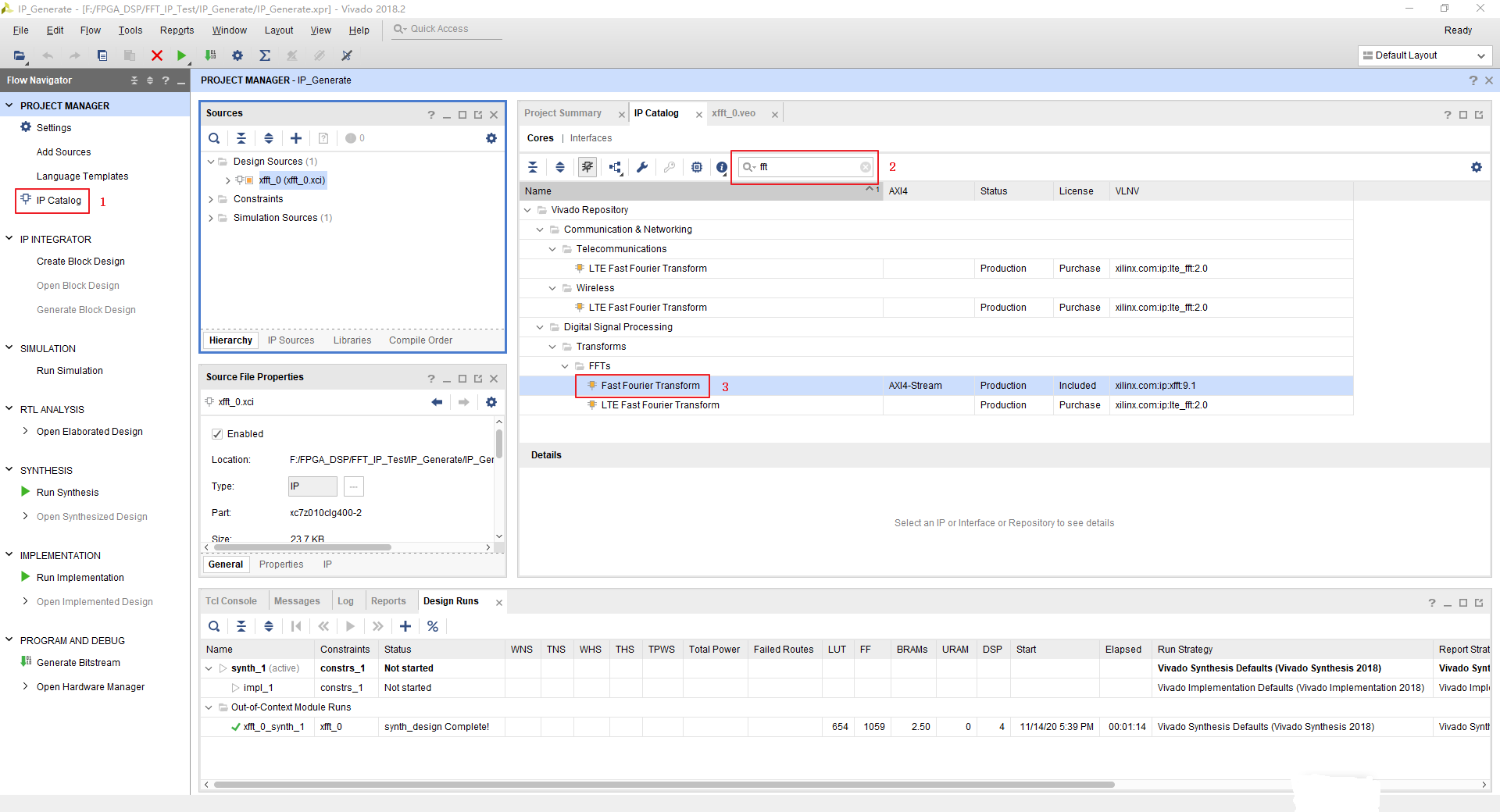
Before using the FFT/IFFT IP core, you need to create it in the Vivado software and configure the relevant parameters. The process is as follows:
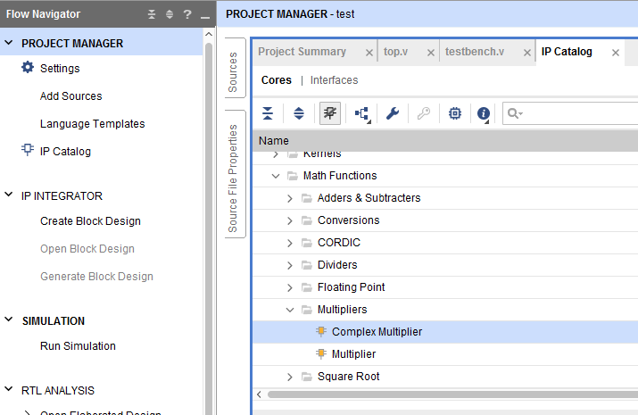
- Find IP core
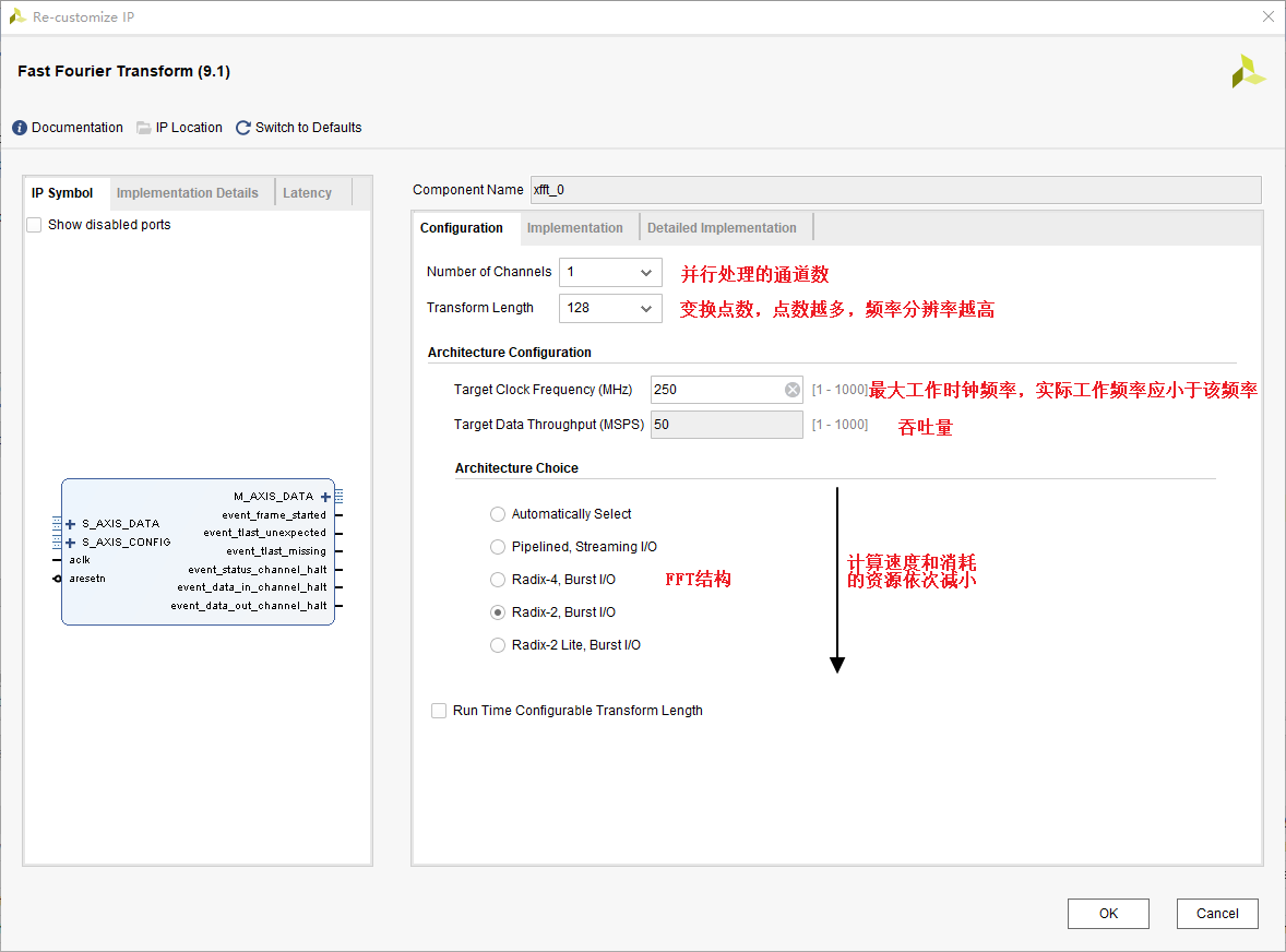
- Perform the configuration under the Configuration window
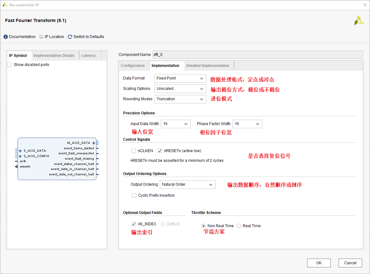
- Carry out the configuration under the Implementation window
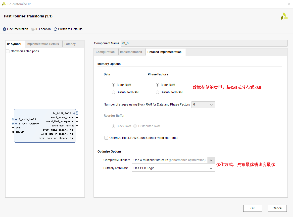
- Carry out the configuration under the Detailed Implementation window
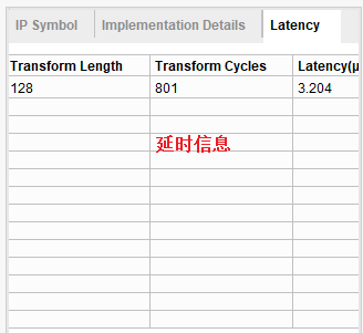
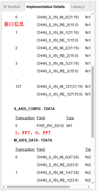
- After the configuration is complete, you can see some specific details of the implementation on the right side of the configuration window
In the following figure, it is particularly important to note that when sending control data to S_AXIS_CONFIG_TDATA, 1 represents the IP core performs the FFT function, and 0 represents the IP core performs the IFFT function. To
2. Actual simulation of FFT/IFFT IP core in Modelsim
Since the implementation of the FFT or IFFT function by the IP core is only a difference in control information, we will take the implementation of the FFT function as an example to introduce a simple simulation process.
Since this is a cross-platform simulation, a specific simulation environment needs to be set up. I will not go into details here. For details, please refer to the following link:How to use Vivado's IP for simulation in QuestaSim or ModelSim
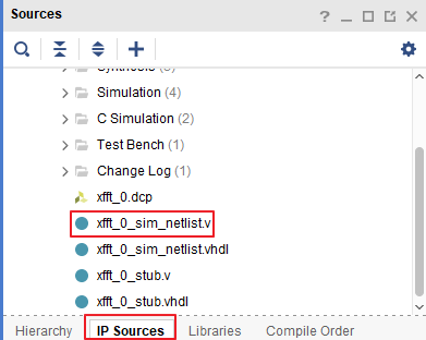
The file we need for simulation is the xxx_netlist.v file. After this file is added to the Modelsim project together with our test file, the simulation can be performed. The location of the file is as shown in the figure below:
Since most of the interfaces of the IP core in Vivado are based on the AXI4-Stream protocol, before writing the test files, you must carefully read and understand the relevant timing of the AXI4-Stream protocol, and then perform correct data reading and writing. For details, please see The link is as follows:AXI4-Stream protocol summary
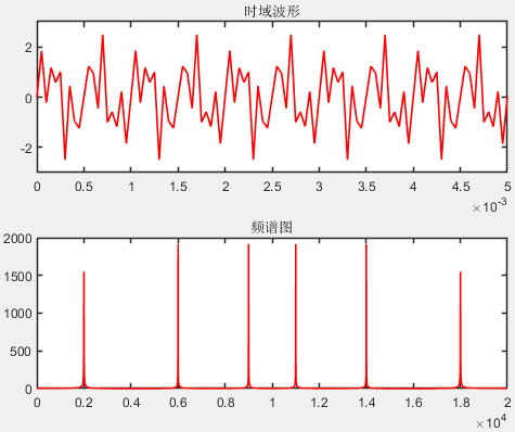
In this test simulation, the simulation data we used is a mixture of three frequency data, and the spectrum analysis is performed. The frequencies are 2KHz, 6KHz and 9KHz respectively. The test data is generated by Matlab. The generated files are as follows:
Fs = 20000;% sampling frequency
 N = 2^12;% of sampling points
 t = 0:1/Fs:N/Fs-1/Fs;% time span
s = sin(2000*2*pi*t) + sin(6000*2*pi*t) + sin(9000*2*pi*t);
figure(1);
subplot(2,1,1);
plot(t,s,'r','LineWidth',1.2);
 title('Time domain waveform');
axis([0,100/Fs,-3,3]);
set(gca,'LineWidth',1.2);
 % Draw a spectrogram
 df1=Fs/(N-1);% resolution
 f1=(0:N-1)*df1;% frequency of each point
 % By default, N=4096 point FFT is done
 %The frequency resolution of FFT with different points is different, the more points, the higher the resolution
 %Such as 128-point FFT, select 128 points from the input signal for Fourier transform, and the output result represents the spectrum information
Y1=fft(s);
subplot(2,1,2);
 % Half of the symmetrical spectrogram
plot(f1,abs(Y1),'r','LineWidth',1.2);
 title('spectrogram');
set(gca,'LineWidth',1.2);
The time-domain waveform and frequency spectrum under Matlab simulation are shown in the figure below:
The Verilog Testbench file is as follows:
`timescale 1 ns / 1 ps
module fft_tb ();
glbl glbl();
reg clk;
reg rst_n;
reg signed [15:0] Time_data_I [127:0];
wire fft_s_config_tready;
reg signed [31:0] fft_s_data_tdata;
reg fft_s_data_tvalid;
wire fft_s_data_tready;
reg fft_s_data_tlast;
wire signed [47:0] fft_m_data_tdata;
wire signed [7:0] fft_m_data_tuser;
wire fft_m_data_tvalid;
reg fft_m_data_tready;
wire fft_m_data_tlast;
wire fft_event_frame_started;
wire fft_event_tlast_unexpected;
wire fft_event_tlast_missing;
wire fft_event_status_channel_halt;
wire fft_event_data_in_channel_halt;
wire fft_event_data_out_channel_halt;
reg [7:0] count;
reg signed [23:0] fft_i_out;
reg signed [23:0] fft_q_out;
reg signed [47:0] fft_abs;
initial begin
clk = 1'b1;
rst_n = 1'b1;
#5 rst_n = 1'b0;
#5 rst_n = 1'b1;
fft_m_data_tready = 1'b1;
$readmemh("F:/FPGA_DSP/FFT_IP_Test/BeforeFilterHex.txt",Time_data_I);
end
always #5 clk = ~clk;
//Send time domain data to FFT IP core, master -> slave
always @(posedge clk or negedge rst_n) begin
if (!rst_n) begin
fft_s_data_tvalid <= 1'b0;
fft_s_data_tdata <= 32'd0;
fft_s_data_tlast <= 1'b0;
count <= 8'd0;
end
else if (fft_s_data_tready) begin//FFT IP core (slave device) is ready to receive data, and the master device starts to send valid data
if(count == 8'd127)begin
fft_s_data_tvalid <= 1'b1;
fft_s_data_tlast<=1'b1;//tlast is set to 1
fft_s_data_tdata <= {16'd0,Time_data_I[count]};
count <= 8'd0;
end
else begin
fft_s_data_tvalid <= 1'b1;
fft_s_data_tlast<=1'b0;//tlast is set to 0
fft_s_data_tdata <= {16'd0,Time_data_I[count]};
count <= count + 1'b1;
end
end
else begin
fft_s_data_tvalid <= 1'b0;
fft_s_data_tlast <= 1'b0;
fft_s_data_tdata <= fft_s_data_tdata;
end
end
//Take the spectrum data out
always @(posedge clk) begin
if (fft_m_data_tvalid) begin
fft_i_out<=fft_m_data_tdata[23:0];
fft_q_out<=fft_m_data_tdata[47:24];
end
end
always @(posedge clk) begin
fft_abs<=$signed(fft_i_out)* $signed(fft_i_out)+ $signed(fft_q_out)* $signed(fft_q_out);
end
//fft ip nuclear instantiation
xfft_0 u_fft(
.aclk(clk), // clock signal (input)
.aresetn(rst_n), // reset signal, active low (input)
.s_axis_config_tdata(8'd1), // ip core setting parameter content, when it is 1, it will do FFT operation, when it is 0, do IFFT operation (input)
.s_axis_config_tvalid(1'b1), // ip core configuration input is valid, can be directly set to 1 (input)
.s_axis_config_tready(fft_s_config_tready), // output wire s_axis_config_tready
//As a slave device when receiving time domain data
.s_axis_data_tdata(fft_s_data_tdata), // The data channel that transmits the time domain signal to the FFT IP core, [31:16] is the imaginary part, [15:0] is the real part (input, master->slave)
.s_axis_data_tvalid(fft_s_data_tvalid), // indicates that the master device is driving a valid transmission (input, master->slave)
.s_axis_data_tready(fft_s_data_tready), // indicates that the slave device is ready to receive a data transmission (output, slave->master), when tvalid and tready are both high, start data transmission
.s_axis_data_tlast(fft_s_data_tlast), // The master device sends a transmission end signal to the slave device (input, master->slave, pull high to end)
//As the main device when sending spectrum data
.m_axis_data_tdata(fft_m_data_tdata), //Spectrum data output by FFT, [47:24] corresponds to the imaginary data, and [23:0] corresponds to the real data (output, master->slave).
.m_axis_data_tuser(fft_m_data_tuser), // The index of the output spectrum (output, master->slave), the value *fs/N is the corresponding frequency point;
.m_axis_data_tvalid(fft_m_data_tvalid), // indicates that the master device is driving a valid transmission (output, master->slave)
.m_axis_data_tready(fft_m_data_tready), // indicates that the slave device is ready to receive a data transmission (input, slave->master), when tvalid and tready are both high, start data transmission
.m_axis_data_tlast(fft_m_data_tlast), // The master device sends a transmission end signal to the slave device (output, master->slave, pull high to end)
//Other output data
.event_frame_started(fft_event_frame_started), // output wire event_frame_started
.event_tlast_unexpected(fft_event_tlast_unexpected), // output wire event_tlast_unexpected
.event_tlast_missing(fft_event_tlast_missing), // output wire event_tlast_missing
.event_status_channel_halt(fft_event_status_channel_halt), // output wire event_status_channel_halt
.event_data_in_channel_halt(fft_event_data_in_channel_halt), // output wire event_data_in_channel_halt
.event_data_out_channel_halt(fft_event_data_out_channel_halt) // output wire event_data_out_channel_halt
);
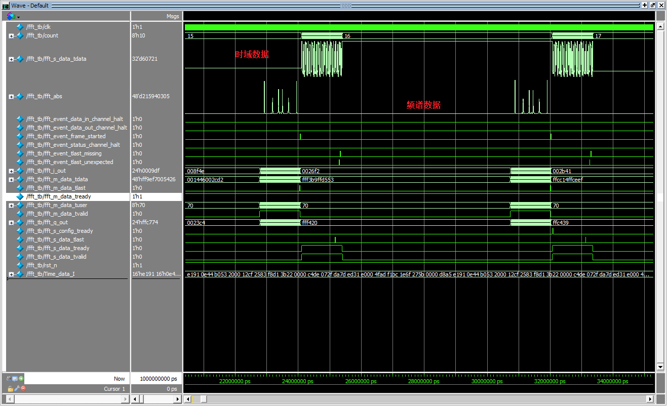
endmoduleThe simulation results are shown in the figure below:
Intelligent Recommendation

Detailed use of Xilinx Vivado (3): Using IP cores
IP core (IP Core) There are many IP cores in Vivado that can be used directly, such as mathematical operations (multipliers, dividers, floating-point operators, etc.), signal processing (FFT, DFT, DDS...

Detailed explanation of the use of XDMA IP based on xilinx vivado
XDMA ip use directory 1 Overview 2 Reference documents 3 Brief description of XDMA 4 XDMA IP configuration 4.1 IP settings page 1 rate and interface selection 4.2 IP Setting Page 2 PCIE ID 4.3 IP Sett...

Fun with Zynq serialization 48-[ex67] Vivado FFT and IFFT IP core application examples
Privileged classmates play Zynq serial 48-[ex67] Vivado FFT and IFFT IP core application examples 1 About Fourier Transform Regarding the Fourier transform, such a magical transform, its basic princip...
FFT Vivado IP core implementation
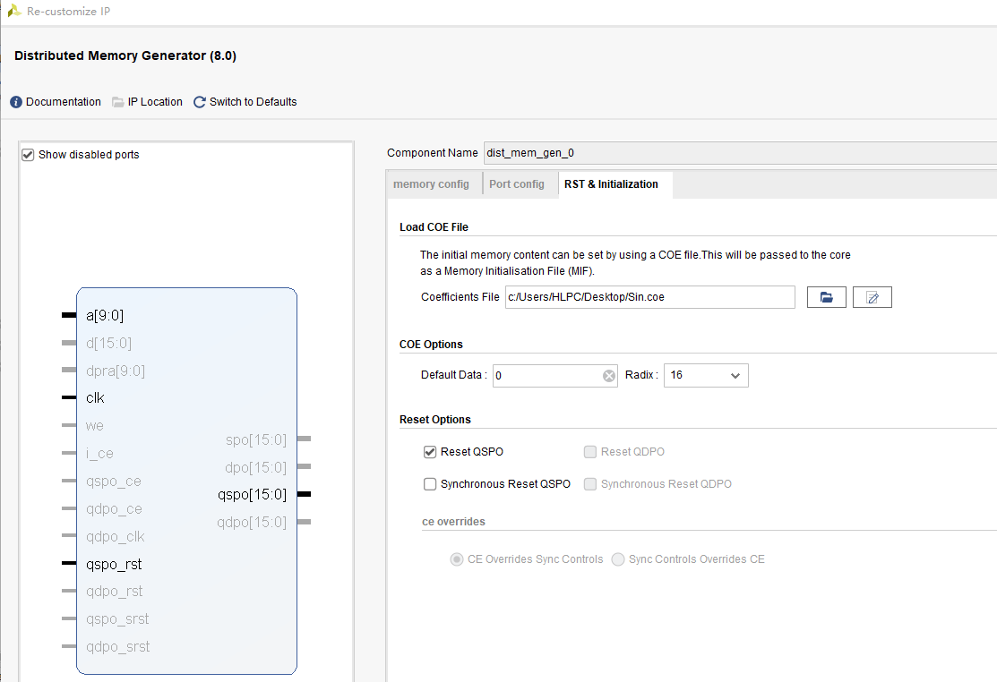
1. First, use matlab to generate 16bit binary sine signal data and store it in rom: 2. Store the data in the rom ip core For the application of rom core, see: https://blog.csdn.net/qq_39005414/article...
Detailed explanation of GTX ip core settings and routine code usage based on xilinx vivado
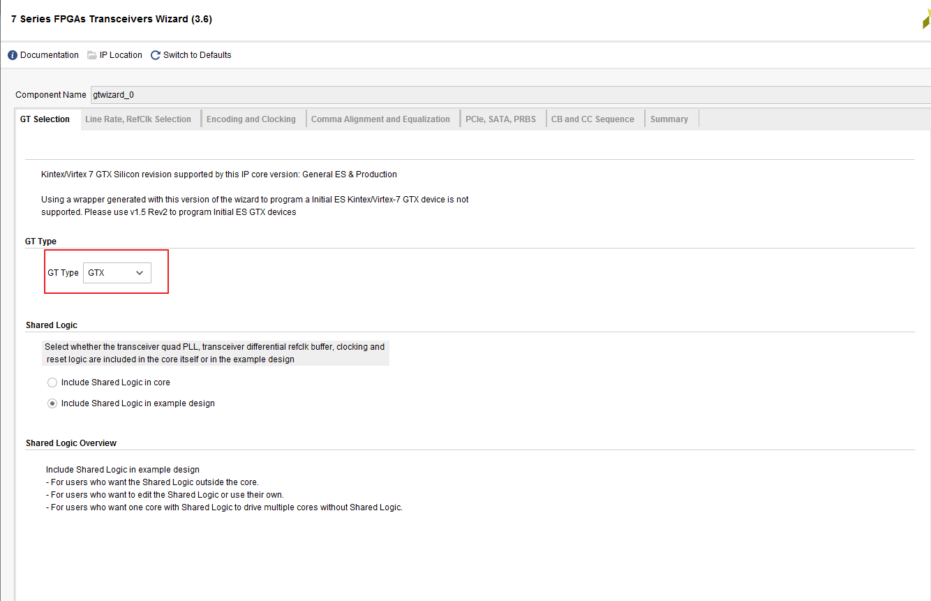
Contents of this article 1 Overview 2 Reference documents 3 IP settings of GTX 3.1 Use environment of this example 3.2 Settings of GTX IP interface 3.2.1 GTX IP settings page 1 3.2.2 GTX IP Settings P...
More Recommendation
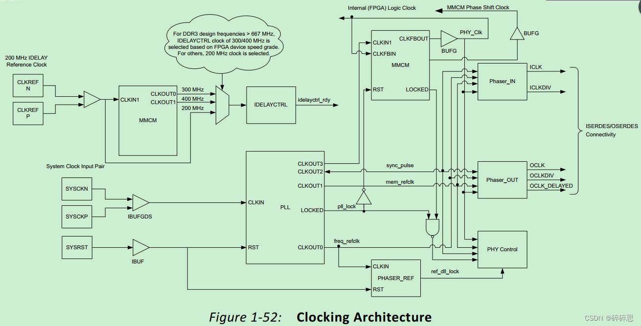
Xilinx vivado DDR3 MIG IP core system clock, reference clock explanation and detailed explanation of the functions of each clock
Note: When using xilinx's MIG core, there will be many clock configurations, which can easily be confused over time. Please record them for quick recollection in the future. If there are any errors, p...

Introduction and simulation of xilinx FFT IP
1 Introduction to xilinx FFT IP XilinxFast Fourier Transform (FFT IP) The kernel implementsCooley-Tukey FFTAlgorithm, which is a computationally effective method for calculating the discrete Fourier t...
Detailed introduction to the IP core call of the multiplier in Vivado and its simulation
The IP core of the multiplier can be found in the picture below The input configuration and output configuration of the IP core is shown below. When we select the multplier construction option, select...

Use of xilinx cordic ip core
This article describes how to use cilinx's CORDIC core to produce a sin and cos waveform? The principle of cordic is not introduced. Baidu has a lot. After we know the principle, we need to use...

The use of Xilinx Uartlite IP core
Creation and connection of PL end IP core Add the IP cores of ZYNQ and axi_uartlite, and automatically connect as shown below: The serial port data transmission can be in polling mode or interrupt mod...