Verilog implementation of "10010" sequence detector and Modelsim simulation
tags: Verilog Modelsim Quartus II Sequence detector
The sequence detector is one of the very common designs in sequential digital circuits. Its main function is to identify a specified sequence from the digital code stream.For example, after receiving a serial code (10010), the detector outputs the flag 1, otherwise, it outputs 0.
This article is quoted from https://blog.csdn.net/llxxyy507/article/details/81019999
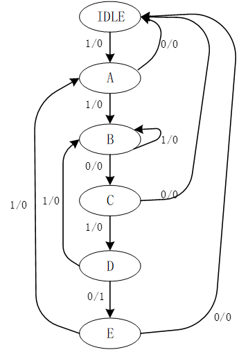
In the "10010" sequence detector, there are 6 states, plus an Idle state, a total of 7 states. But you can first reduce the amount of Verilog code by simplifying the state. The initial state analysis is shown in the table below.

It can be seen that the state "Idle" and the state "0", "10010" under the same input, the next state is exactly the same as the output, so it can be reduced to a state, after all the states are simplified, the state is named and encoded .


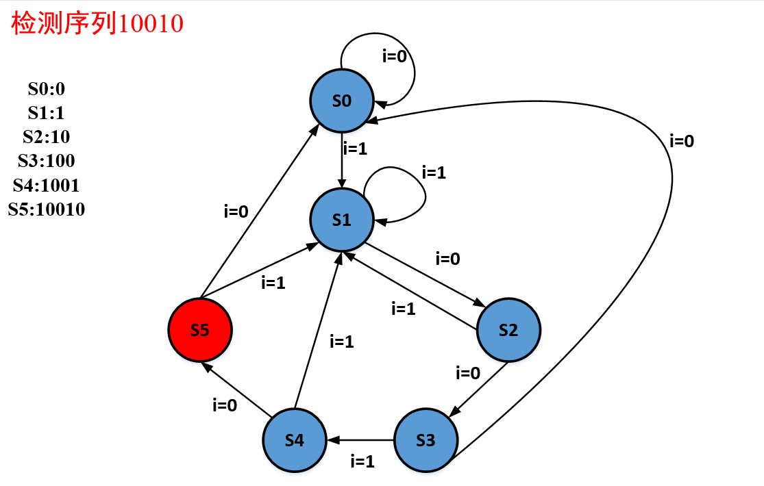
Name the states of "Idle", "1", "10", "100", and "1001" respectively as "Idle", "S1", "S10", "S100", and "S1001". The Verilog program is as follows:
module seq_detector(seq,clk,rst,b);       // detector "10010"
input seq,clk,rst;
output b;

reg b;
reg [4:0]state;

parameter Idle  = 5'b1_0000,
          S1    = 5'b0_1000,
          S10   = 5'b0_0100,
          S100  = 5'b0_0010,
          S1001 = 5'b0_0001;

always @(posedge clk or negedge rst)     //low active
  if (!rst) begin
              state <= Idle;
              b <= 0;
             end
  else
      case(state)
     Idle: if( seq == 0)
              begin
                state <= Idle;
                b <= 0;
              end
           else
              begin
                state <= S1;
                b <= 0;
              end

     S1: if( seq == 0)
              begin
                state <= S10;
                b <= 0;
              end
           else
              begin
                state <= S1;
                b <= 0;
              end

     S10: if( seq == 0)
              begin
                state <= S100;
                b <= 0;
              end
           else
              begin
                state <= S1;
                b <= 0;
              end

     S100: if( seq == 0)
              begin
                state <= Idle;
                b <= 0;
              end
           else
              begin
                state <= S1001;
                b <= 0;
              end

     S1001: if( seq == 0)
              begin
                state <= Idle;
                b <= 1;
              end
           else
              begin
                state <= S1;
                b <= 0;
              end

      default state <= 5'bx;
    endcase
endmodule
The testbench files are as follows:
`timescale 1ns/1ns
`define halfperiod 20

module t;
reg clk,rst;
reg [23:0]data;
wire seq,b;
assign seq = data[23];

initial
  begin
    clk = 0;
    rst = 1;
    #2 rst = 0;
    #30 rst = 1;
    data = 20'b1100_1001_0000_1001_0100;
    #(`halfperiod * 1000)$stop;
  end

always #(`halfperiod) clk = ~clk;
always @(posedge clk)
         #2 data = {data[22:0],data[23]};

seq_detector m(.seq(seq), .clk(clk), .rst(rst), .b(b) );

endmodule
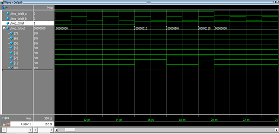
The results obtained through Modelsim simulation are as follows:

It can be seen that after seq occurs in the "10010" sequence, b can detect the input of the sequence and output a high level.
Intelligent Recommendation
Sequence detector (10010)
This is the practice of Xiayu Wen Teacher Chapter 15. See the book. Here is my practice content. In the process I have written, I have encountered some problems. 1. Two AlWays blocks are used in writi...
10010 sequence detector
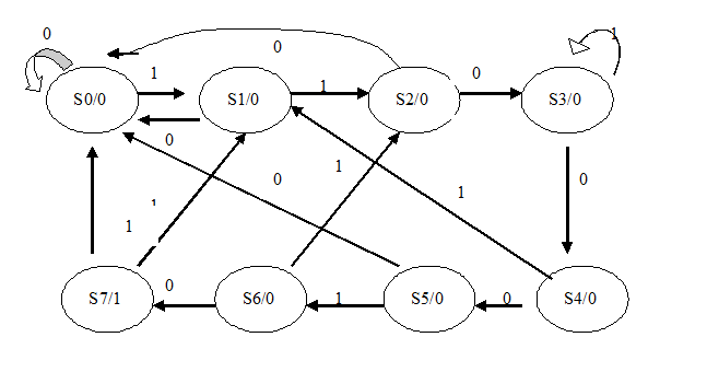
Platform: Notepad ++ & vivado2017.4 10010 sequence detector is a very simple state machine instance testbench Simulation waveform Output Z Input X After the change of 10010 (status between 1-5 con...
Ten Verilog Based on Modelsim (4) (Digital Display Frequency Meter + Sequence Detector) - Program + Test Code + Waveform + Result Analysis
content Experiment 1: Design of 7 people Experiment 2: Design of Calculation Logic Unit Experiment 3: Design of JK Trigger Experiment 4: Design of Ring Counter Experiment 5: Design of order arrangemen...

Sequence detector (detects "10010 sequence")
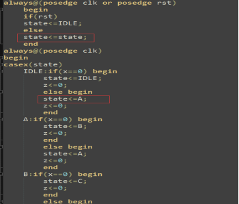
IDLE is the initial state, A represents the first state "1", B represents the second state "10", C represents the third state "100", and D represents the fourth State &qu...
Verilog sequence detector-two cases
1 Sequence detectors are used in the fields of data communication, radar and telemetry to detect step identification signs. It is a circuit used to detect one or more sets of sequence signals. For e...
More Recommendation
Verilog Programming -1.10010 Sequence Detector
Verilog Programming -1.10010 Sequence Detector Background The sequence detector has a full application in the field of data communication, radar, and telemetry, sequence detection using Verilog langua...
Verilog writes "11010" sequence detector
The sequence detector is one of the very common designs in the timing digital circuit. Its main function isIdentify a specified sequence from the digital code stream. The sequence detector has two mai...
Sequence detector based on System Verilog
This article realizes a 10010 sequence detector through System Verilog Status machine design The state machine is a very important concept in digital circuit design. Many complex controls can be compl...
Verilog language realizes overlapping sequence detector (10010) (Mealy type and Moore type)
1.Mealy type The output is not only related to the current state, but also related to the input 1.1 Code (three-stage) 1.2 Simulation results 2.Moore type The output is only determined by the current ...

Verilog design a digital clock (ModelSim simulation)
Verilog design a digital clock (ModelSim simulation) Author: Yan Yong Cheng QQ: 793805481 Design a digital clock that can display hours, minutes and seconds through 6 seven-segment digital tubes, as s...