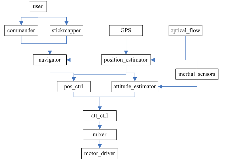
Px4 source code structure diagram
The purpose of this blog is to have an overall understanding of the px4 project, an understanding of the flow of each signal, and the control framework used by the control algorithm.
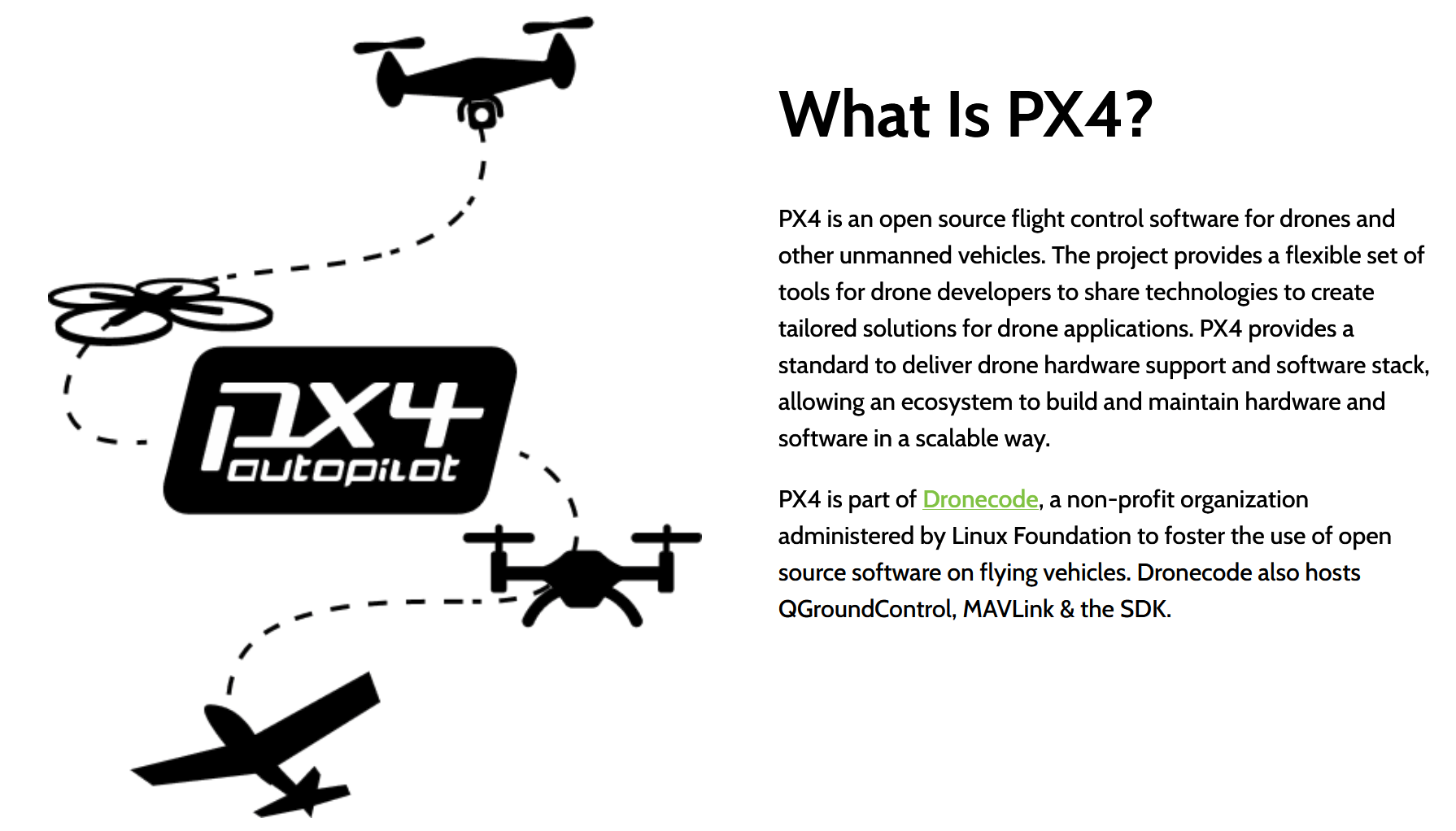
PX4 autopilot softwareCan be divided into three parts: real-time operating system, middleware and flight control stack.
1.NuttX real-time operating system
Provide POSIX-style user operating environment (such as printf (), pthreads, / dev / ttyS1, open (), write (), poll (), ioctl ()) Task scheduling.
2. PX4 middleware
PX4 middleware runs on top of the operating system, providing device drivers and a micro object request broker (uORB) for asynchronization between individual tasks running on the pilot Communication. After Px4 was open sourced by 3DR, the entire code structure was changed, the original system was abandoned, and Nuttx was adopted, but the core idea has not changed-in order to simplify development and use a message passing mechanism that sacrifices some efficiency, this is the most essential of Px4 and ArduPilot difference.
3. PX4 flight control stack
The flight control stack can use the PX4 control software stack or other control software, such as APM: Plane, APM: Copter, but it must run on PX4 middleware.
This part can be divided into
Decision navigation part: According to the aircraft's own safety status and received commands, decide which mode to work in and what to do next.
Position and attitude estimation part: According to the sensor to get its own position and attitude information, this part of the algorithm has the highest gold content, and there are quite a few algorithms.
Position and attitude control part: design the control structure according to the desired position and attitude, and achieve the desired position and attitude as quickly and stably as possible.
Controller output part: mixer and actuator, PWM limiter.


Algorithm inFirmware / src / modules, driven byFirmware/src/drivers
px4 native firmware module list:
System command program
mavlink-Send and receive mavlink information through the serial port
sdlog2-Save system logs / flight data to SD card
tests-Test procedures in the test system
top-List the current process and CPU load
uORB- Micro Object Request Broker-Distribute information between other applications
drive
mkblctrl--Blctrl electronic module driver
esc_calib-ESC calibration tool
fmu-Definition of FMU pin input and output
gpio_led——– GPIO LED driver
gps-GPS receiver driver
pwm-Update rate command of PWM
sensors-Sensor application
Flight control procedures
Flight safety and navigation
commander-Main flight safety state machine
navigator-Mission, fail-safe and RTL navigator
Estimate pose and position
attitude_estimator_ekf-Attitude estimation based on EKF
ekf_att_pos_estimator-Estimation of pose and position based on EKF
position_estimator_inav– Position estimation for inertial navigation
multirotor attitude and position controller
mc_att_control--Multirotor attitude controller
mc_pos_control--Multirotor position controller
fixedwing attitude and position controller
fw_att_control-Attitude control of fixed-wing aircraft
fw_pos_control_l1-Fixed wing position controller
VTOL attitude controller
vtol_att_control——Vertical take-off and landing attitude controller
3.1 Decision
3.1.1 Task decision. Mission-oriented, mission decision mainly decides where to go next for the multi-rotor. Further, the path needs to be planned so that the whole process can meet the requirements such as flying to the waypoint and flying along the route, and flying to the waypoint and obstacle avoidance .
3.1.2Health management and failure protection. Taking safety as the guide, the failure protection mainly decides where to go next for the multi-rotor. Before or during the flight of a multi-rotor aircraft, communication failures, sensor failures, and abnormal power systems may occur. These accidents will directly lead to the inability to complete control tasks. This part includes the introduction of safety issues, health assessment of airborne equipment, health monitoring of airborne equipment, and protection recommendations after failure.
Sensor calibrationinside commander
The corresponding program is in Firmware / src / modules / commander andFirmware/src/modules/navigator
Complete task mode switching, taking into account information such as battery power, GPS and other sensors are working properly.

- commander
- orb_publish(ORB_ID(home_position), homePub, &home);
- orb_publish(ORB_ID(offboard_mission), mission_pub, &mission);
- orb_publish(ORB_ID(vehicle_control_mode), control_mode_pub, &control_mode);
- orb_publish(ORB_ID(vehicle_status), status_pub, &status);
- orb_publish(ORB_ID(actuator_armed), armed_pub, &armed);
- orb_publish(ORB_ID(vehicle_command_ack), command_ack_pub, &command_ack);
- orb_copy(ORB_ID(vehicle_status), state_sub, &state);
- orb_copy(ORB_ID(parameter_update), param_changed_sub,¶m_update;
- orb_copy(ORB_ID(manual_control_setpoint), sp_man_sub, &sp_man);
- orb_copy(ORB_ID(offboard_control_mode), offboard_control_mode_sub, &offboard_control_mode);
- orb_copy(ORB_ID(telemetry_status), telemetry_subs[i], &telemetry);
- orb_copy(ORB_ID(sensor_combined), sensor_sub, &sensors);
- orb_copy(ORB_ID(differential_pressure), diff_pres_sub, &diff_pres);
- orb_copy(ORB_ID(system_power), system_power_sub, &system_power);
- orb_copy(ORB_ID(safety), safety_sub, &safety);
- orb_copy(ORB_ID(vtol_vehicle_status), vtol_vehicle_status_sub, &vtol_status);
- orb_copy(ORB_ID(vehicle_global_position), global_position_sub, &gpos);
- orb_copy(ORB_ID(vehicle_local_position), local_position_sub, &local_position);
- orb_copy(ORB_ID(vehicle_attitude), attitude_sub, &attitude);
- orb_copy(ORB_ID(vehicle_land_detected), land_detector_sub, &land_detector);
- orb_copy(ORB_ID(battery_status), battery_sub, &battery);
- orb_copy(ORB_ID_VEHICLE_ATTITUDE_CONTROLS, actuator_controls_sub, &actuator_controls);
- orb_copy(ORB_ID(subsystem_info), subsys_sub, &info);
- orb_copy(ORB_ID(position_setpoint_triplet), pos_sp_triplet_sub, &pos_sp_triplet);
- orb_copy(ORB_ID(vehicle_gps_position), gps_sub, &gps_position);
- orb_copy(ORB_ID(mission_result), mission_result_sub, &mission_result);
- orb_copy(ORB_ID(geofence_result), geofence_result_sub, &geofence_result);
- orb_copy(ORB_ID(vehicle_command), cmd_sub, &cmd);
- navigator
- orb_publish(ORB_ID(position_setpoint_triplet), _pos_sp_triplet_pub, &_pos_sp_triplet);
- orb_publish(ORB_ID(mission_result), _mission_result_pub, &_mission_result);
- orb_publish(ORB_ID(geofence_result), _geofence_result_pub, &_geofence_result);
- orb_publish(ORB_ID(vehicle_attitude_setpoint), _att_sp_pub, &_att_sp);
- orb_copy(ORB_ID(vehicle_global_position), _global_pos_sub, &_global_pos);
- orb_copy(ORB_ID(vehicle_gps_position), _gps_pos_sub, &_gps_pos);
- orb_copy(ORB_ID(sensor_combined), _sensor_combined_sub, &_sensor_combined);
- orb_copy(ORB_ID(home_position), _home_pos_sub, &_home_pos);
- orb_copy(ORB_ID(navigation_capabilities), _capabilities_sub, &_nav_caps);
- orb_copy(ORB_ID(vehicle_status), _vstatus_sub, &_vstatus)
- orb_copy(ORB_ID(vehicle_control_mode), _control_mode_sub, &_control_mode)
- orb_copy(ORB_ID(parameter_update), _param_update_sub, ¶m_update);
- orb_copy(ORB_ID(vehicle_command), _vehicle_command_sub, &cmd);
3.2 Position estimation and attitude estimation
This part requires a lot of theoretical knowledge, which is temporarily lacking.
sensorsIt is a processing of gyroscope and accelerometer geomagnetic meter
- sensors
- orb_publish(ORB_ID(airspeed), _airspeed_pub, &_airspeed);
- orb_publish(ORB_ID(differential_pressure), _diff_pres_pub, &_diff_pres);
- orb_publish(ORB_ID(battery_status), _battery_pub, &_battery_status);
- orb_publish(ORB_ID(rc_channels), _rc_pub, &_rc);
- orb_publish(ORB_ID(manual_control_setpoint), _manual_control_pub, &manual);
- orb_publish(ORB_ID(actuator_controls_3), _actuator_group_3_pub, &actuator_group_3);
- orb_publish(ORB_ID(sensor_combined), _sensor_pub, &raw);
- orb_copy(ORB_ID(sensor_accel), _accel_sub[i], &accel_report);
- orb_copy(ORB_ID(sensor_gyro), _gyro_sub[i], &gyro_report);
- orb_copy(ORB_ID(sensor_mag), _mag_sub[i], &mag_report);
- orb_copy(ORB_ID(sensor_baro), _baro_sub[i], &_barometer);
- orb_copy(ORB_ID(differential_pressure), _diff_pres_sub, &_diff_pres);
- orb_copy(ORB_ID(vehicle_control_mode), _vcontrol_mode_sub, &vcontrol_mode);
- orb_copy(ORB_ID(parameter_update), _params_sub, &update);
- orb_copy(ORB_ID(rc_parameter_map), _rc_parameter_map_sub, &_rc_parameter_map);
- orb_copy(ORB_ID(input_rc), _rc_sub, &rc_input);
- ardrone_interface
- orb_publish(ORB_ID(actuator_outputs), pub, &outputs);
- orb_copy(ORB_ID_VEHICLE_ATTITUDE_CONTROLS, actuator_controls_sub, &actuator_controls);
- #define ORB_ID_VEHICLE_ATTITUDE_CONTROLS ORB_ID(actuator_controls_0)
- orb_copy(ORB_ID(actuator_armed), armed_sub, &armed);
- batt_smbus
- orb_publish(_batt_orb_id, _batt_topic, &new_report);
- orb_copy(ORB_ID(battery_status), sub, &status)
- bma180
- orb_publish(ORB_ID(sensor_accel), _accel_topic, &report);
- GPS
- orb_publish(ORB_ID(vehicle_gps_position), _report_gps_pos_pub, &_report_gps_pos);
- orb_publish(ORB_ID(satellite_info), _report_sat_info_pub, _p_report_sat_info);
- hmc5883
- orb_publish(ORB_ID(sensor_mag), _mag_topic, &new_report);
- hott
- orb_publish(ORB_ID(esc_status), _esc_pub, &esc);
- orb_copy(ORB_ID(sensor_combined), _sensor_sub, &raw);
- orb_copy(ORB_ID(battery_status), _battery_sub, &battery);
- orb_copy(ORB_ID(airspeed), _airspeed_sub, &airspeed);
- orb_copy(ORB_ID(esc_status), _esc_sub, &esc);
- l3gd20
- orb_publish(ORB_ID(sensor_gyro), _gyro_topic, &report);
- lsm303d
- orb_publish(ORB_ID(sensor_accel), _accel_topic, &accel_report);
- orb_publish(ORB_ID(sensor_mag), _mag->_mag_topic, &mag_report);
- mpu6000
- orb_publish(ORB_ID(sensor_accel), _accel_topic, &arb);
- orb_publish(ORB_ID(sensor_gyro), _gyro->_gyro_topic, &grb);
- mpu9250
- orb_publish(ORB_ID(sensor_accel), _accel_topic, &arb);
- orb_publish(ORB_ID(sensor_gyro), _gyro->_gyro_topic, &grb);
- ms5611
- orb_publish(ORB_ID(sensor_baro), _baro_topic, &report);
- pwm_out_sim
- orb_publish(ORB_ID(actuator_outputs), _outputs_pub, &outputs);
- orb_copy(_control_topics[i], _control_subs[i], &_controls[i]);
- actuator_controls_s _controls[actuator_controls_s::NUM_ACTUATOR_CONTROL_GROUPS];
- orb_copy(ORB_ID(actuator_armed), _armed_sub, &aa);
- px4flow
- orb_publish(ORB_ID(optical_flow), _px4flow_topic, &report);
- orb_publish(ORB_ID(distance_sensor), _distance_sensor_topic, &distance_report);
- orb_publish(ORB_ID(subsystem_info), pub, &info);
- px4fmu
- orb_publish(ORB_ID(actuator_outputs), _outputs_pub, &outputs);
- orb_publish(ORB_ID(safety), _to_safety, &safety);
- orb_publish(ORB_ID(input_rc), _to_input_rc, &_rc_in);
- orb_copy(_control_topics[i], _control_subs[i], &_controls[i]);
- orb_copy(ORB_ID(actuator_armed), _armed_sub, &_armed);
- orb_copy(ORB_ID(parameter_update), _param_sub, &pupdate);
- px4io
- orb_publish(ORB_ID(vehicle_command), pub, &cmd);
- orb_publish(ORB_ID(safety), _to_safety, &safety);
- orb_publish(ORB_ID(battery_status), _to_battery, &battery_status);
- orb_publish(ORB_ID(servorail_status), _to_servorail, &_servorail_status);
- orb_publish(ORB_ID(input_rc), _to_input_rc, &rc_val);
- orb_publish(ORB_ID(actuator_outputs), _to_outputs, &outputs);
- orb_publish(ORB_ID(multirotor_motor_limits), _to_mixer_status, &motor_limits);
- orb_copy(ORB_ID(actuator_armed), safety_sub, &safety);
- orb_copy(ORB_ID(vehicle_command), _t_vehicle_command, &cmd);
- orb_copy(ORB_ID(parameter_update), _t_param, &pupdate);
- orb_copy(ORB_ID(actuator_controls_0), _t_actuator_controls_0, &controls);
- orb_copy(ORB_ID(actuator_controls_x), _t_actuator_controls_0, &controls);
- orb_copy(ORB_ID(vehicle_control_mode), _t_vehicle_control_mode, &control_mode);
- stm32(adc)
- orb_publish(ORB_ID(system_power), _to_system_power, &system_power);
3.3 Position control and attitude control


3.4pwm output
3.4.1mixer
The content corresponding to the official address (expired)
The mixer output defines how the controller output is mapped to the motor and servo output. All built-in mixer files are located in the / etc / mixers directory of the ROM file system and are compiled into firmware. Mixer is a set of independent mappers that read from the control and write to the output of the actuator. A module combines a set of inputs based on predefined rules and parameters to produce a set of outputs.

Mixer is defined as a text file, with a capital letter followed by a colon. All other lines are ignored, which means that explanatory text can be mixed with the definition. Each file can define multiple Mixers. The number of actuator outputs produced by a Mixer is specific.
The starting form is as follows:
<tag>:<mixer arguments>
The label selects the type of Mixer, "M" is a simple summing Mixer, "R" is a multi-rotor (multi-rotor) Mixer, etc.
An empty Mixer does not consume control and produces an output of the actuator, its value is always zero. Usually an empty Mixer is used as a placeholder Mixer set to achieve a specific mode of brake output.
Empty Mixer definition form:
Z:
(2) Simple Mixer
The beginning of a simple Mixer:
M: <control count>
O: <-ve scale> <+ve scale> <offset> <lower limit> <upper limit>
If it is zero, the output is zero, and the fixed value output by Mixer is limited.
The second line defines the output scaler and scalar parameters. Although the calculation is performed as a floating point operation, the value stored in the definition file is scaled by 10000 times, and the -0.5 offset is encoded as -5000.
This definition continues to describe the control input and zoom items:
S: <group> <index> <-ve scale> <+ve scale> <offset> <lower limit> <upper limit>
These values define the control group reading data from those scalers and the offset of the values within the group. It is specific to the device reading Mixer's definition.
When used for hybrid vehicle control, the mixer group 0 is the vehicle attitude control group, and the index values from 0 to 3 are usually: roll, pitch, yaw, thrust.
For details, see: https://pixhawk.org/dev/mixing?s[]=mixer
(3) Multi-rotor Mixer
The multi-rotor mixer combines four control inputs (roll, pitch, yaw, thrust) into a set of brake output for driving the motor speed controller.
The form defined by Mixer:
R: <geometry> <roll scale> <pitch scale> <yaw scale> <deadband>
Parameter explanation:
Machinery: including quad (4x, 4+), hex (6x, 6+), octo (8x, 8+)
Individual roll, pitch and yaw control factors
Motor output dead zone

Intelligent Recommendation
Vtol_att_control source code analysis in PX4
Analysis of source code of vtol attitude control in px4 The /src/modules/vtol_att_control/ folder contains vtol_att_control_main, vtol_type, standard/tailsitter/tiltrotor and other files. Here is the ...
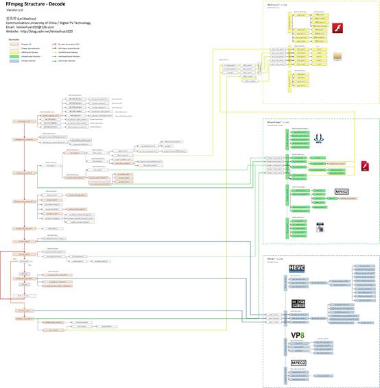
FFmpeg source code structure diagram decoding
Share the artificial intelligence tutorial of my teacher, God! Zero basis, easy to understand! You are also welcome to reprint this article. Sharing knowledge, benefiting the people and realizing the ...
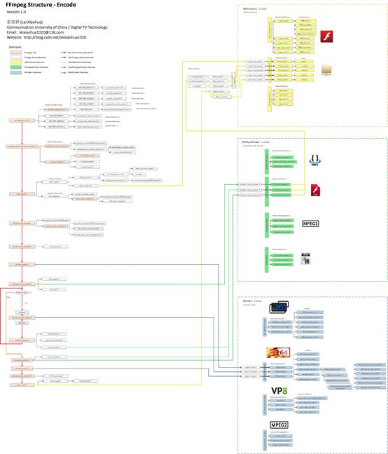
FFmpeg source code structure diagram - coding
Share the artificial intelligence tutorial of my teacher, God! Zero basis, easy to understand! You are also welcome to reprint this article. Sharing knowledge, benefiting the people and realizing the ...
Android framework source code structure diagram
turn! turn! turn! https://blog.csdn.net/iqingfen/article/details/44703035 Keep your own Android framework source code structure diagram for your own convenience. The first 6 will be involved in the ba...
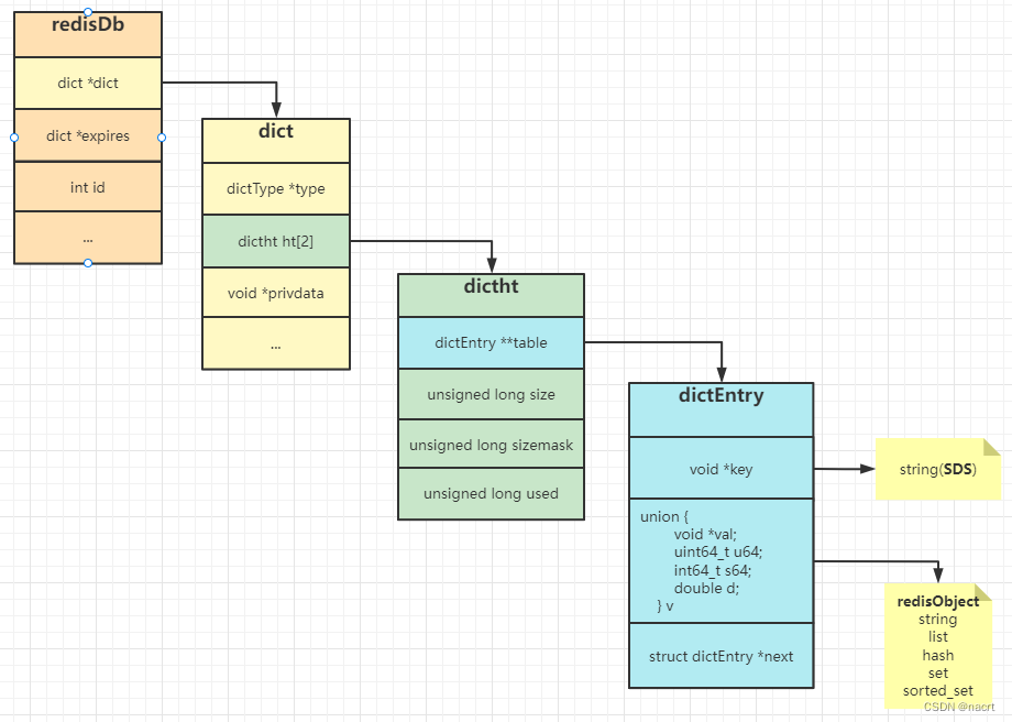
some source code data structure diagram of redis
1. Some characteristics of redis Non -relationalKey valueThe database, the bottom layer is hashtable, can be taken out or inserted into the correlation value according to the time complexity of 0 (1) ...
More Recommendation
redis source code reading 4-structure diagram
Partial structure and redis-cli, redis-server structure diagram ZSkipList (structzskiplist) ZSet (structzset) listTypeEntry Struct (structlist_type_entry) redis DB structure diagram (structredis_db) r...

PX4 native firmware source code analysis (pit digging)--1. Code structure
write at the beginning I recently started to learn the PX4 source code and carried out secondary development. I suffered from the lack of analysis of the PX4 source code on the Internet, so I opened a...
PX4 source code learning two--PX4 environment construction
Ubuntu16.04 environment setup: If the cross-compilation chain cannot be downloaded with apt, use the following method. Next, download the source code and compile: Generally speaking, as long as there ...

PX4 code reading notes (1) - code structure
PX4 has a good reputation and is currently the mainstream open source flight control project, and is used as a reference for flight control development by many companies. The project code can be downl...
PX4 open source engineering structure is concise introduction
PX4 open source engineering structure is concise introduction Step1 get open source code 1.1 Open source code version 1.2 clone open source code Step2 understand the project situation 2.1 Support mode...