The rookie-Autosar COM module and communication analysis-study notes
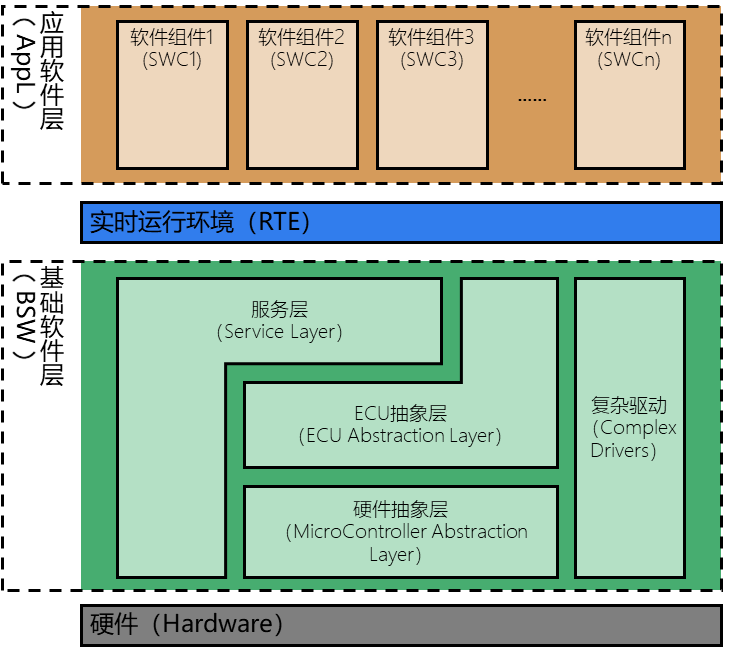
1. Architecture and terminology
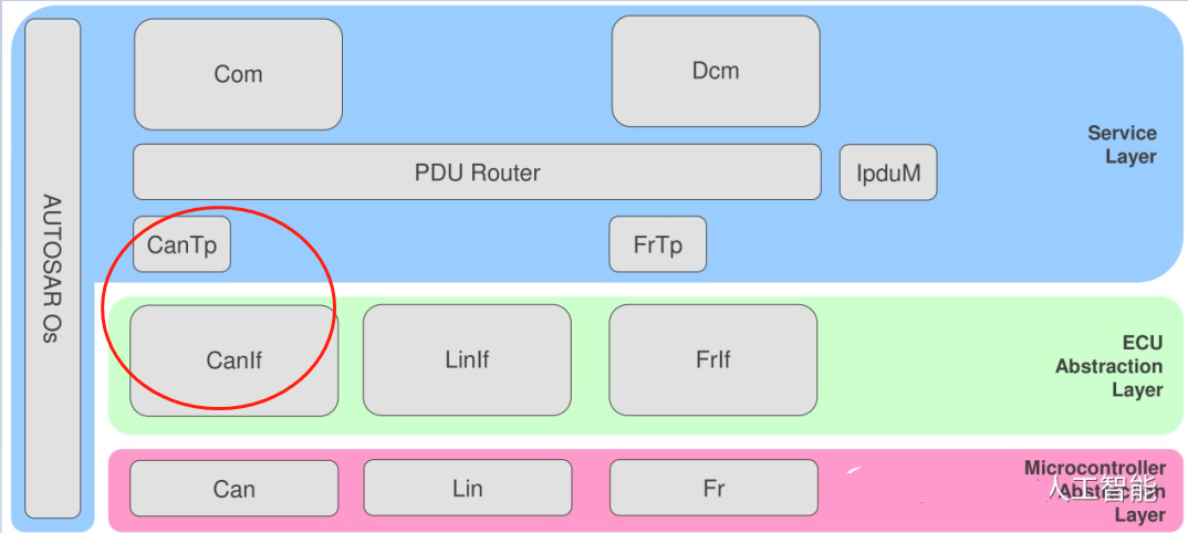
• PDU Router: PDU——Protocol Data Unit, protocol data unit. The function of this module is to distribute the signal data sent by COM to the corresponding protocol bus; or to turn different protocols into the same signal and upload it to COM.
• IPDU Mux: Used to resolve some special protocols, such as CAN FD or some user-defined protocols. It plays the role of a unified CAN ID and different signal Layout
• CAN Tp: Sub-packet data transmission and error detection, generally only used for diagnosis
• CAN Interface: It has nothing to do with the hardware. What is related to the hardware is the work done by the following two Drivers. This Interface can mainly configure the sending and receiving queues; framing (FlexRay); managing time to trigger the bus schedule (LIN, FlexRay)
• CAN Driver: It is the driver package of CAN module on the main chip in MCAL
• Trcv Driver: Trcv-the abbreviation of Transceiver, which means transceiver driver. If it is an external CAN transceiver, Trcv Driver is used here instead of CAN Driver.
It feels so simple to list the above terms. Maybe you still don’t understand it. The following is a simple explanation of the sending and receiving process (CAN is too large and I can’t finish it for a while, so let’s explain it in the simplest way. a bit)
2. Sending process
- Application layer Send a data into COM
- COM write signal into PDU Buffer
- The PDU is sent by the PDU Router immediately or periodically (each PDU has an independent ID), and then the PDU Router recognizes the bus type and sends the PDU to different lower-level modules
- Interface writes packets into different queues according to different channels
- Driver immediately sends the message according to the priority of the message
Three, receiving process
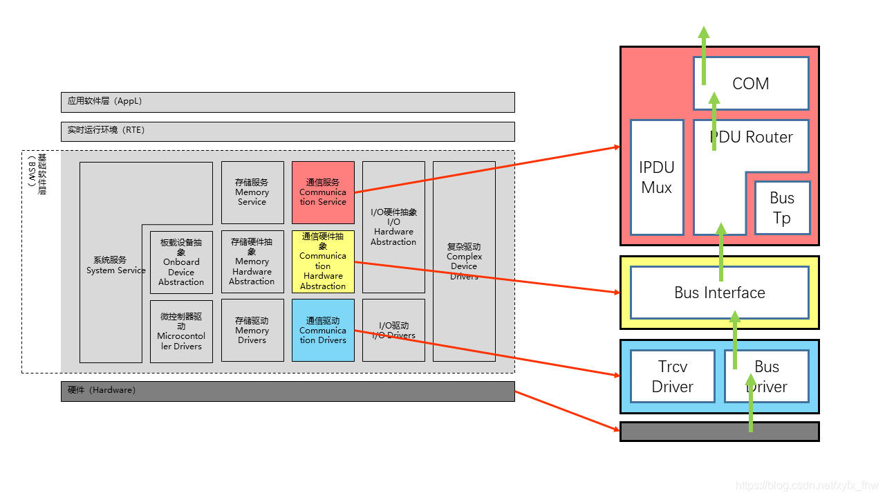
Interrupt or cyclic reception (here assumed to be interrupt): - Hardware receive message
- The Rx interrupt (function) is issued by the Driver, and then the data is passed to the Interface through RxIndication
- Pass to PDU Router
- Pass to COM (if SWCs use Data ReceptionTrigger, notify RTE; otherwise, temporarily store in Buffer)
- The signal is read by RTE and then read by the application layer
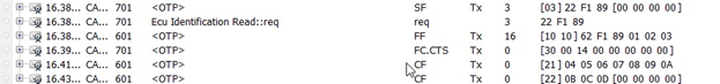
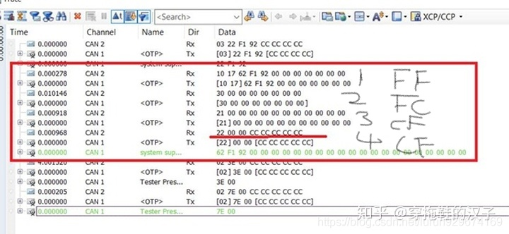
Four, CANTP communication data analysis
**3.1 There are two CAN/CANFD transmission methods for CANTP **
CANFD: It can be understood as an upgraded version of the CAN protocol, only the protocol has been upgraded, and the physical layer has not changed.
The main difference between Can and CanFD: different transmission rate, different data length (CAN-8byte/CANFD-64byte), different frame format, and different ID length.
3.2 Format of CAN Frame
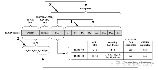
CAN ID: Identifies the identification number of this specific ECU. The length is divided into 11 bits and 29 bits. The standard frame uses 11 bits as ID identification, and the extended frame uses 29 bits as ID identification.
The arbitration field of the extended frame has 29 bits, 2^29 messages can appear, and there are gaps on the data link (transparent to the operator).
The arbitration field of the standard frame is continuous 11 bits, and 2^11 types of messages can appear;
In fact, the CAN standard frame and the extended frame are only different in the length of the ID, in order to be able to expand more CAN nodes and better support the upper layer protocol.。
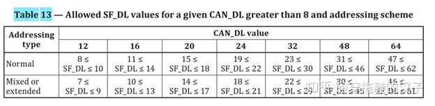
The length of the data carried by the database depends on whether it is Classical CAN or CAN FD. The length of the former data field is 8 bytes. The length of the CAN FD data field depends on OEM requirements, and the range is 8 bytes—64 bytes. Of course, the length is not arbitrarily selected, please refer to the following table:
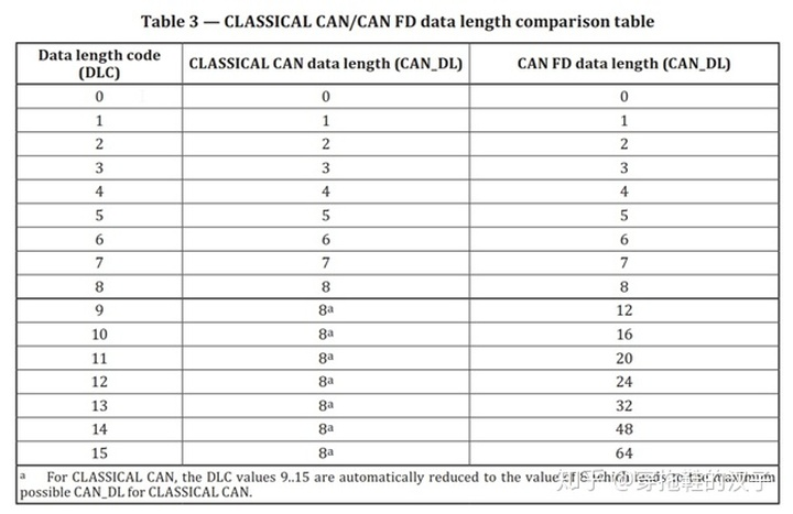
After more than 8 bytes, the length can be defined according to the length in the table.
**
Classical CAN
First, share the classic CAN single-frame and multi-frame transmission data.
When the data length is less than or equal to 8 bytes (because there is PCI, the actual useful data length is 7 bytes), use a single frame (Single Frame);
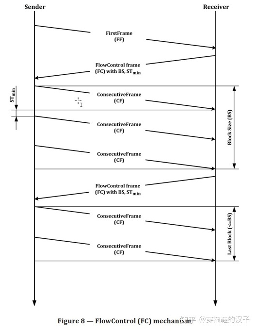
When the data length is greater than 8 Bytes, the multi-frame transmission in TP is used. It is equivalent to unpacking, sending, and grouping data larger than 8 Bytes in the data transmission process, where the first frame (First Frame), flow control frame (Flow Control), and continuous frame (Consecutive Frame) are used.
The above frame format is defined as follows in ISO 15765-2:
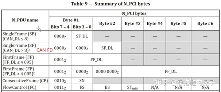
Define different frame types for different values of the first Byte bit in the data frame:
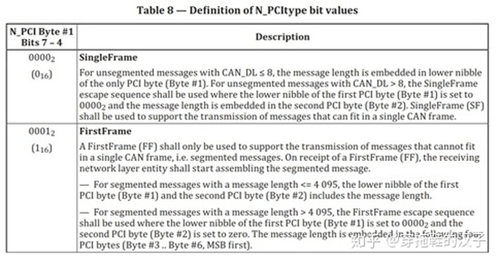
1. The high 4 bits are 0 to indicate a single frame, and the low 4 bits value defines the frame length;
2. For a single frame when the data length is greater than 8 bytes (for CAN FD), the first byte value is 0, and the second byte value marks the data length of this single frame;
3. The high 4 bits is 1 to mark the first frame, the low 4 bits and the second byte mark the data length (the maximum FFF length is 4095 bytes), which is suitable for multi-frame data length less than or equal to 4095;
4. When the multi-frame data length is greater than 4095 bytes, the high 4 bits is 1 to indicate the first frame, the low 4 bits and the second byte are set to 0, and Byte 3—byte 6 indicates the frame length;
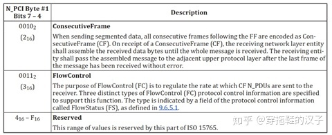
5. The upper 4 bits are 2 to indicate continuous frames, and the lower 4 bits indicate the serial numbers of consecutive frames;
6. The upper 4 bits are 3 to indicate the flow control frame, and the lower 4 bits indicate the flow state (Flow State) of the flow control frame. Byte 2 is BS (Block Size), and Byte 3 is STmin. The specific meanings of FS, BS and STmin are as follows:
· FS (FlowStatus) indicates whether the sending network entity can continue message transmission. The specific meaning is detailed in ISO 15765:
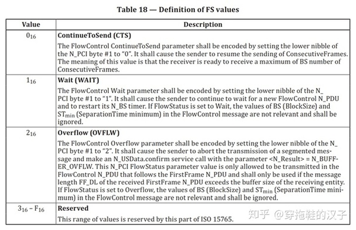
· BS (BlockSize) indicates the number of consecutive frames sent before the next flow control frame (FC). In segmented data transmission, only the last block of ConsecutiveFrames may be smaller than the number of BS frames.

When the BS value is 0, for the sender (Sender) it means that the receiver (Receiver) will not send flow control frames next, and the sender will send all consecutive frames to the receiver.
· STmin is the Separation Time minimum (STmin) parameter definition. This parameter is defined by the receiver and means the minimum interval between two consecutive frames.
**
CAN FD
The data length of CAN FD transmission data frame is defined as follows
1) The data length of single frame transmission is as defined in the protocol:
According to the range of data length, select the applicable length.
(2) For multi-frame transmission, after the data length is defined, the first frame and the following continuous frames are transmitted according to the defined data length, and the last continuous frame is transmitted according to the above Table 13. Specific examples are as follows:
If the defined data field length is 12 bytes, the data length to be transmitted is 23 bytes, the first frame and the first subsequent frame, the data field length is 12 bytes, the last frame depends on the remaining data length, and it is sent according to Table 13.
Reference link:
https://blog.csdn.net/weixin_33289873/article/details/112678827
https://blog.csdn.net/xyfx_fhw/article/details/98731632
Intelligent Recommendation
COM programming study notes
When analyzing viruses in peacetime, it is inevitable to encounter some COM, and it is a headache when analyzing this. I found an article written by a foreigner, which is easy to understand, followed ...
Autosar learning notes - (2) BSW module
Autosar learning notes - (2) BSW module 1. The role of BSW 2. Structure of BSW 2.1 MCAL hardware abstract layer 2.1.1 I / O drive (I / O Drivers) 2.2 Communication Drivers (Communication Drivers) 2.3 ...
Python's Bluetooth communication module pybluez study notes
Install Bluetooth communication module pybluez Installation of pybluez under Windows Note: The development environment of this article is Windows10+Python3.7.3 During the installation process, the fol...

Liteos study notes -4 communication module AT framework
Liteos study notes -4 communication module AT framework I. Introduction to the AT client What is an AT client? AT client framework Second, serial port driver framework implementation 2.1 serial port i...
Liteos study notes -3 communication module AT instruction
Liteos study notes -3 communication module AT instruction First, an experimental environment Second, ESP8266 common basic instructions Third, connection remote server communication based on TCP protoc...
More Recommendation
Automotive electronic study notes---AutoSAR overview
Automotive electronic study notes—AutoSAR overview 1 Overview Automotive Open System ARchitecture, Automotive Open System Architecture 2. Architecture 1) Architecture diagram 2) Detailed descrip...
Automotive electronic study notes---AutoSAR RTE
Automotive electronic study notes-RTE of AutoSAR -1. Concept 1) RTE is the realization of the AUTOSAR virtual function bus (Virtual Function Bus, VFB) interface. It provides basic services for the com...
Autosar Study Notes: Network Management NM
There are thousands of ECU nodes on the car. It is impossible for all ECUs to start working when ignition. Instead, when the user needs to request the relevant functions, the relevant ECU nodes partic...
Rookie redemption study notes
1. Memory Management: Managed by JVM stack All new objects and member variables The life cycle of member variables: exists when the object is created, and disappears when the object is recycled Garbag...
The study notes rookie js
Learn, the more the feeling will not be more. php + mysql learn a fur. We do know that the web is to be combined with the company began js the project js start learning journey () submit event submit ...