ADC analog to digital converter (parallel comparison type)

Success is not only the future, but decided to do the moment, continued accumulation.

I chose the topic is class-based ADC, Topics requirements: Input:0 5VDC, Output: sixTTL Level, Conversion rate: ≥ 1kHz, Output availableLED Light indication. I have designed a circuit and weld the circuit board, but also the honor to the teachers and students were opening report. Then talk about my design it!
Chapter IX textbook is about the number of electric conversion of ADC and DAC conversion, but describes the contents of the ADC circuit design is small, just introduced a bit ADC0809 chip. I found a topic parallel comparison type ADC circuit, as well as in after-school exercise in the circuit diagram, this led to the idea. The title is a three-way circuit, I figured out if this principle can do road shows 6 ~


Whole frame, from left to right is the input voltage circuit, a reference voltage divider circuit, a comparison circuit, register circuit, an encoding circuit, TTL output logic gate circuit and the LED display circuit.
Here I did not put two cascaded 74LS148 encoders, each is counted. Because the subject is required output display like six-way, not say a six-bit representation ah. If I cascade chip two 74148, then, my output is 2 ^ 6 planted, according to the design principle of the parallel comparator circuits, I want to comparator circuit for comparing the 64 times, in order to have 64 states shown in the output circuit, .
I refer to BCD, four binary number can represent decimal numbers, I want to express an octal number with three binary numbers, in terms of quantity but also just good ~ two 74ls148 represent three high and three low, they are independent of each other, just 0-7 Effect of the input signal by the input from the encoder. The results are shown in FIG conversion formula, of course, is high and display three results have third output, if only the lower three bits of the words displayed on the lower three bits calculated in accordance with equation like.
So I can not have 64 times the voltage comparator. The key is not so much the variety of chips. Circuit is simply a lot of it ~
Such conversion unit display has three problems:
(1) chip or too much use. For example, I would press the top of the circuit diagram I designed it, I still want to compare the voltage of 16, even with a LM339N integrated chip, I have to use at least four LM339N to do the comparison; if it is not large enough, then take a look at it register circuit, edge D flip-flop 74LS74 chip, a chip register a maximum of two input, that is what I want 16 of D flip-flop, then you need at least eight chips; these were not the circuit and coding chip logic gates, of course, various VCC and the GND, the connection pin is a big problem.
(2) The formula is too cumbersome. Another hit a new data display method, it should not be a problem ideologically acceptable, but obviously not as good as octal or binary to decimal of convenient and direct. Two chips and then to add the weights respectively summed together, then the logical operator can be calculated, but also to modify the output from the output equation.
(3) does not display visual output. Although the output can be done in the six LED, can be determined according to the input voltage and the lamp much light from the bottom, but the output is displayed after the first formula to get out, we can not directly see how much the value resolution .
For more ideas easily circuit design, I made a decision, just six-way comparison. Our task is only required to display the output of six-way ah, since it did not say is six-bit display, I can use showed six 16-bit output, why can not I use 6 showed six of output it? Since the output is six, I just like the six-way comparison voltage, ah, do not have the encoder, these do not 74LS00 logic gates, and the circuit can be simplified a lot from oh ~
Directly on the map it!
After simplifying the circuit, and instantly simply a half ah! ! ! Gray often happy, I could not wait to solder the circuit board, and hey.
And then the circuit simplified conduct some analysis:
Advantages: (1) simple circuit. That is no doubt ah, not just a simple drawing, designing circuit boards is simple ah! Design ideas are clearer and more clear.
(2) with fewer elements to facilitate electrical connection.
(3) LED output visual display, to distinguish between each of the values ​​are also led Vref * 1/6. The higher the level of the electrical input, the more upwardly the light led from the light, and I count results can be obtained about the Ui.
Disadvantages: (1) as compared to 64-bit, 16-bit result of comparison 6 comparison result would obviously lower the resolution. However, in this title the highest accuracy can be achieved Vref * 1/12, it is sufficient to use the.
As CP pulse signal, I can think of is given in two ways:
(1) direct input pulse signal, just as we do the same as the number of electrical experiments;
(2) make a pulse signal source. Timer 555 can be a multivibrator, as shown,According to the formula,Disposed about the values ​​R1, R2 and capacitor C enough.

Intelligent Recommendation

ADC analog to digital conversion

ADC primary means: 1、SAR, Successive approximation register. Successive approximationADC, English abbreviation SAR successive approximation register in each conversion process, by traversing all the q...

Analog Analog/Digital Conversion (ADC)

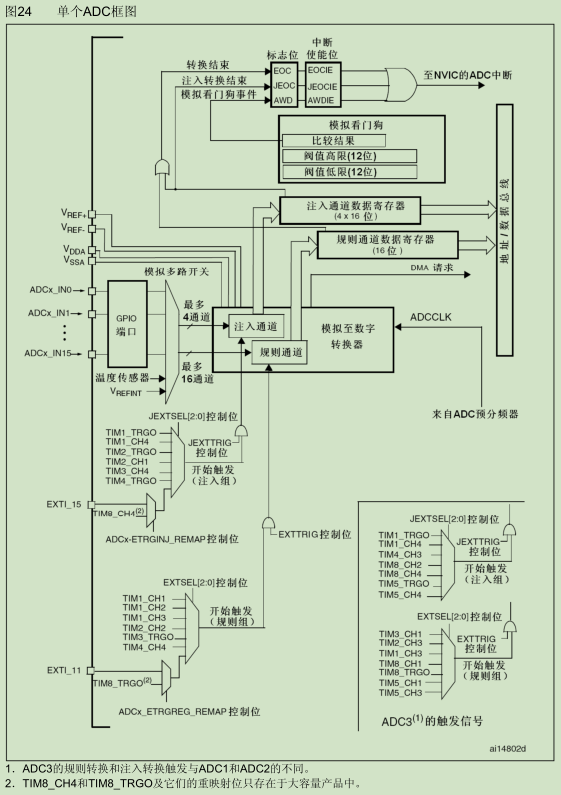
One, ADC introduction 12-bit ADC is a successive approximation analog-to-digital converter. It has up to 18 channels and can measure 16 external and 2 internal signal source. The A/D conversion of eac...

Analog to digital converter ADS112C04

IIC function see the previous blog...

51 series single chip C language programming ADC analog / digital converter program template

[img]http://dl.iteye.com/upload/attachment/598956/b8204d93-2cc5-3eac-b06b-1b5e58cfdf53.jpg[/img] Above - 8-bit ADC program module (for STC12C2052AD series) Above - 8-bit ADC application example (for S...

Embedded knowledge-ARM bare metal-study notes (12): ADC analog to digital converter

Embedded knowledge-ARM bare metal-study notes (12): ADC analog to digital converter 1. ADC 1. What is ADC ADC(analog digital converter):Analog to digital conversion(That is, analog quantity is convert...

More Recommendation

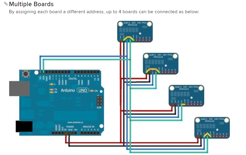
Raspberry Pi ADC module ADS1115 16-bit analog-to-digital converter (python3)

ADC digital to analog conversion wiring VDD - 5V GND - GND SCL - SCL SDA - SDA ADDR - GND A0-A0 of MQ sensor When the ADDR pin is connected to GND, the address is: 0x48 (0100, 1000B) When the ADDR pin...

The basic working principle of the ADC analog-to-digital converter and development readme: 2021-08-06

The basic working principle of the ADC analog-to-digital converter and development readme Sampling, holding, quantifying, encoding Rule: The type of analog signal (single pole and bipolar) and voltage...

ADC analog to digital conversion module

General basics ADC module is an important part of embedded applications, embedded systems and the outside world is the link connection is an important part in monitoring and control system.   ADC...

STM32 ADC-Analog to Digital Conversion

1. Introduction to ADC The STM32F103 series has 3 ADCs with a precision of 12 bits. The ADC is a successive approximation analog-to-digital converter, and each ADC has 18 channels, which can measure 1...

Copyright  DMCA © 2018-2026 - All Rights Reserved - www.programmersought.com  User Notice

Top