An example of the configuration of multiple ENSP clients to achieve intercommunication through Layer 3 switches and routers
tags: ENSP Layer 3 switch router vlan

Five clients successfully communicated with each other through two switches, one core switch, and one router.
First configure each client's IP and gateway, in order:
P1:ip: 10.0.1.2. Subnet mask: 255.255.255.0 Gateway: 10.0.1.1
P2:ip: 10.0.2.2. Subnet mask: 255.255.255.0 Gateway: 10.0.2.1
P3:ip: 10.0.3.2. Subnet mask: 255.255.255.0 Gateway: 10.0.3.1
P4:ip: 10.0.4.2. Subnet mask: 255.255.255.0 Gateway: 10.0.4.1
P5:ip: 10.0.52 Subnet mask: 255.255.255.0 Gateway: 10.0.51
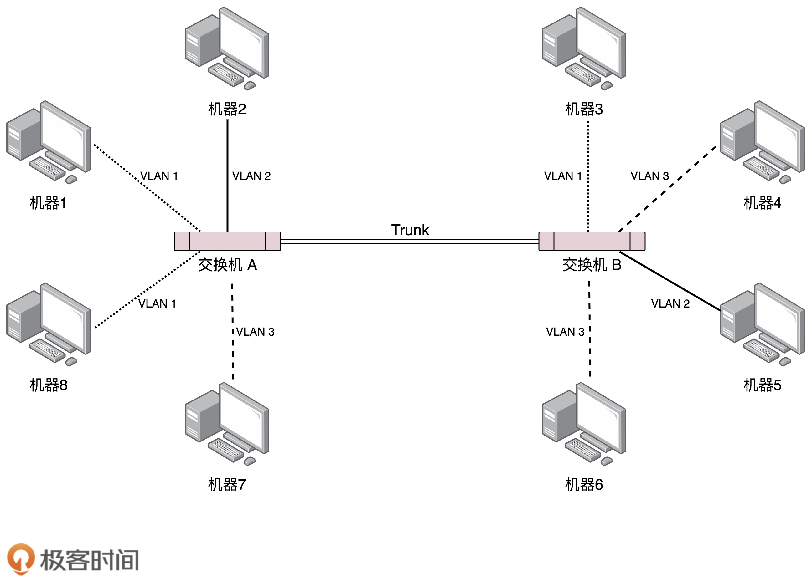
Configure LSW2, set the interface mode of ports G0/0/2, G0/0/3 to ACCESS, and assign them to two VLANs: vlan2, vlan3. Set G0/0/1 The interface mode is TRUNK.
<huawei>undo terminal monitor
<huawei>sys
[huawei]
#
vlan batch 2 to 3
#
interface GigabitEthernet0/0/1
 port link-type trunk
 port trunk allow-pass vlan all
#
interface GigabitEthernet0/0/2
 port link-type access
 port default vlan 2
#
interface GigabitEthernet0/0/3
 port link-type access
 port default vlan 3
Also configure LSW3, set the interface mode of ports G0/0/2, G0/0/3 to ACCESS, and assign them to two VLANs: vlan 4, vlan 5. Set the interface mode of G0/0/1 to TRUNK.
After finishing configuring the core switch LSW1, set the interface mode of G0/0/2, G0/0/3 to TRUNK. Then create a new vlan from 2 to 6, and set the IP address of each vlan to each gateway address. Set the interface mode of G0/0/1 to ACCESS and add it to VLAN 6. Finally, set the static routing address of the switch
#
sysname Huawei
#
vlan batch 2 to 6
#
interface Vlanif1
#
interface Vlanif2
 ip address 10.0.1.1 255.255.255.0
#
interface Vlanif3
 ip address 10.0.2.1 255.255.255.0
#
interface Vlanif4
 ip address 10.0.3.1 255.255.255.0
#
interface Vlanif5
 ip address 10.0.4.1 255.255.255.0
#
interface Vlanif6
 ip address 10.0.6.1 255.255.255.0
#
interface MEth0/0/1
#
interface GigabitEthernet0/0/1
 port link-type access
 port default vlan 6
#
interface GigabitEthernet0/0/2
 port link-type trunk
 port trunk allow-pass vlan all
#
interface GigabitEthernet0/0/3
 port link-type trunk
 port trunk allow-pass vlan all
#
ip route-static 10.0.5.0 255.255.255.0 10.0.6.2
#
Finally, set the router AR2, set the IP of the two interfaces, and the static routing address.
#
interface GigabitEthernet0/0/0
 ip address 10.0.6.2 255.255.255.0
#
interface GigabitEthernet0/0/1
 ip address 10.0.5.1 255.255.255.0
#
ip route-static 0.0.0.0 0.0.0.0 10.0.6.1 //Any network segment will jump to 10.0.6.1
#
Test the connectivity of each client.

Intelligent Recommendation
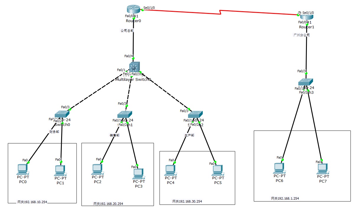
2 routers, 4 Layer 2 switches, and 1 Layer 3 switches to realize network interconnection
The router on the left represents the inside, the router on the right represents the outsideAfter setting up, everything can be pinged Finance Department VLAN10, 192.168.10.1/2 (two PCs) Sales departm...
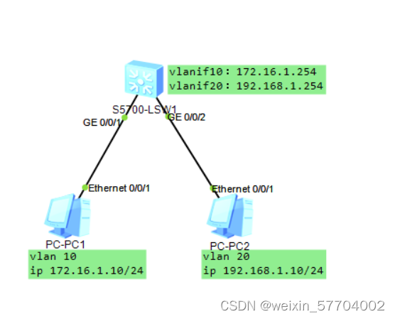
Implement inter-VLAN routing by using Layer 3 switches on ensp
Principle overview: VLAN logically divides a physical LAN into multiple broadcast domains. Hosts in a VLAN can communicate directly, but they cannot communicate directly between VLANs. In real network...
Huawei Ensp Simulator Experiment: Layer 3 Switches Inter-VLAN Communication
The three-layer switch vlan communicates with each other, and the topology diagram is as follows Set up the topology diagram of the experimental environment and start the experiment. I won’t giv...
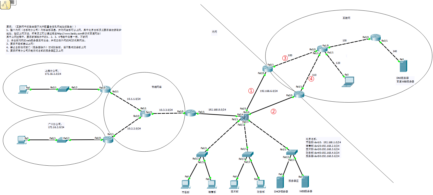
Comprehensive experiments based on routers, switches, vlan, ARP, Layer 3 switches, HSRP, ACL, NAT
Through the previous learning of routers, switches, vlan, ARP, three-layer switches, HSRP, ACL, NAT, and dynamic routing, I have a further understanding and learning of network construction and planni...
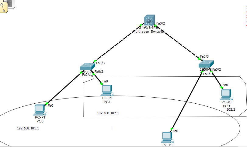
Configuration between Layer 3 and Layer 2 switches
Ding ~~~~~~~~~~~~ I'm coming! ! ! ! ! ! Layer 3 switch configuration: The topology diagram is as follows: Purpose: Communicate between pc0 and pc2, and communicate between pc1 and pc3. The step...
More Recommendation

STP configuration of Layer 2 and Layer 3 switches
Configuring STP for Layer 2 Switching Goal: There may be communication failures caused by line failures in the second-tier network, and the network interruption caused by a line failure can be elimina...
[Huawei ENSP Simulator] The core configuration gateway realizes the intercommunication of multiple network segments
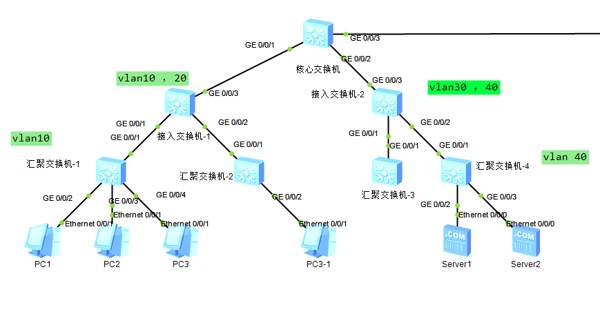
First attach the network topology diagram: The aggregation switch is not configured with any policy, and the access switch is connected foolishly; the gateways of all network segments are configured o...
Ensp Layer 2 link aggregation configuration example
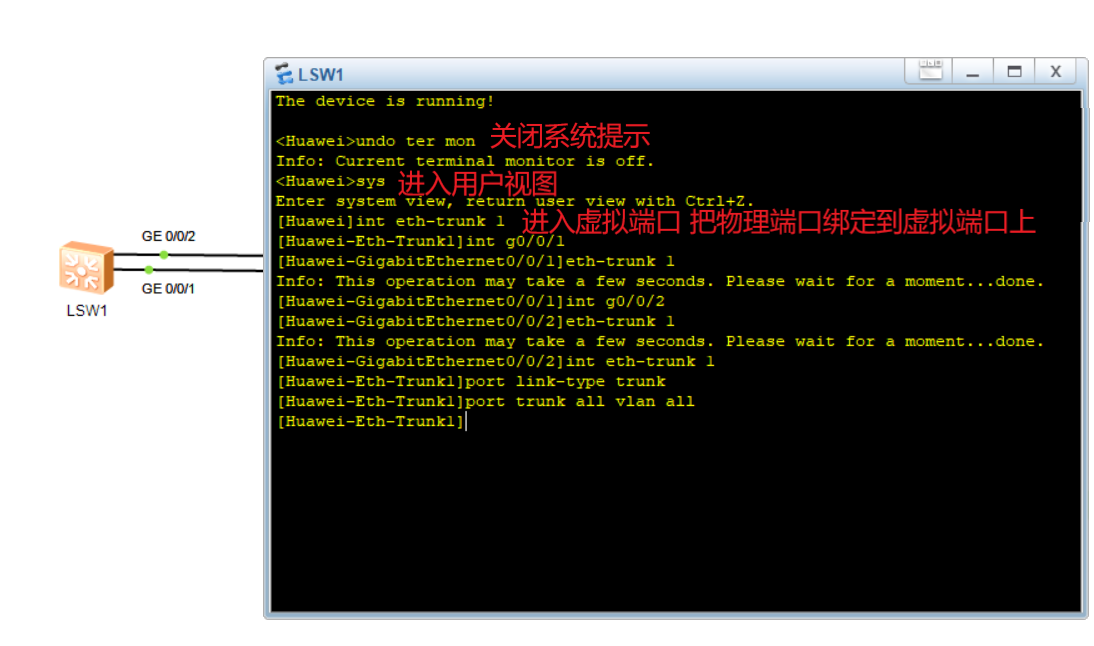
Ensp Layer 2 link aggregation configuration example Link aggregation refers to the aggregation of multiple physical ports to form a logical port to achieve load sharing of outgoing and incoming traffi...
4. Network layer: Layer 3 physical equipment: hubs, switches, routers [IP, ICMP, BGP, OSPF
4. Network layer: Layer 3 physical equipment: hubs, switches, routers [IP, ICMP, BGP, OSPF 1. Hub (the device on the first floor, just use it directly without changing anything) 2. Link layer switch (...
Implementation of vlanif configuration under eNSP simulation (one aggregation switch, two access switches) through the three-layer switch to realize the three-layer communication between VLANs
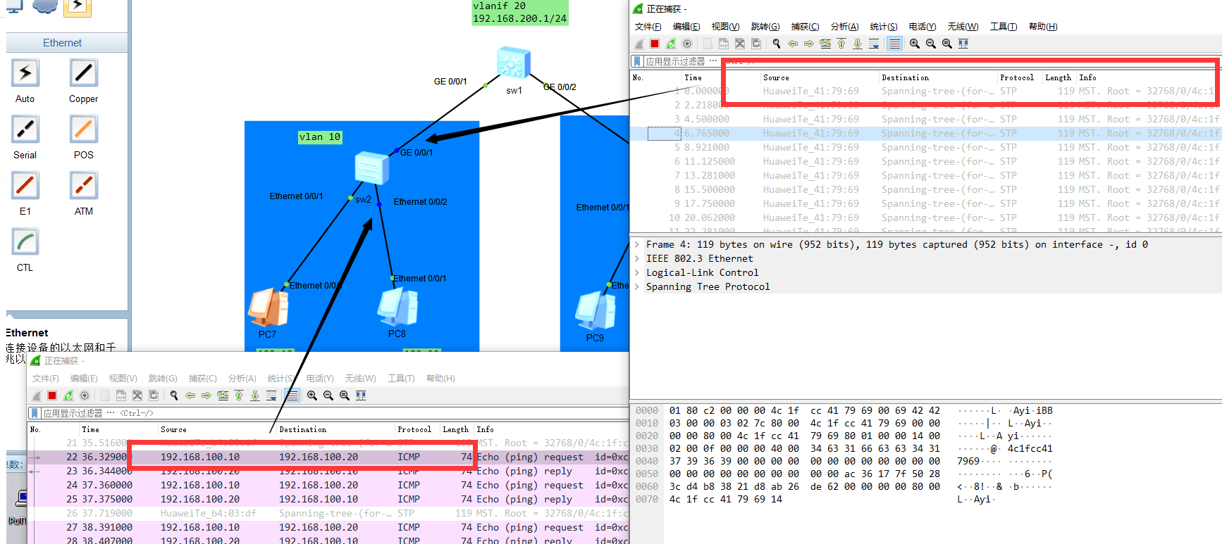
Experimental topology map: Problem analysis: Because this topology is a three-layer device. The access switches (sw2, sw3) are forwarding devices. You can regard vlan 10 as a PC as a whole, and simila...