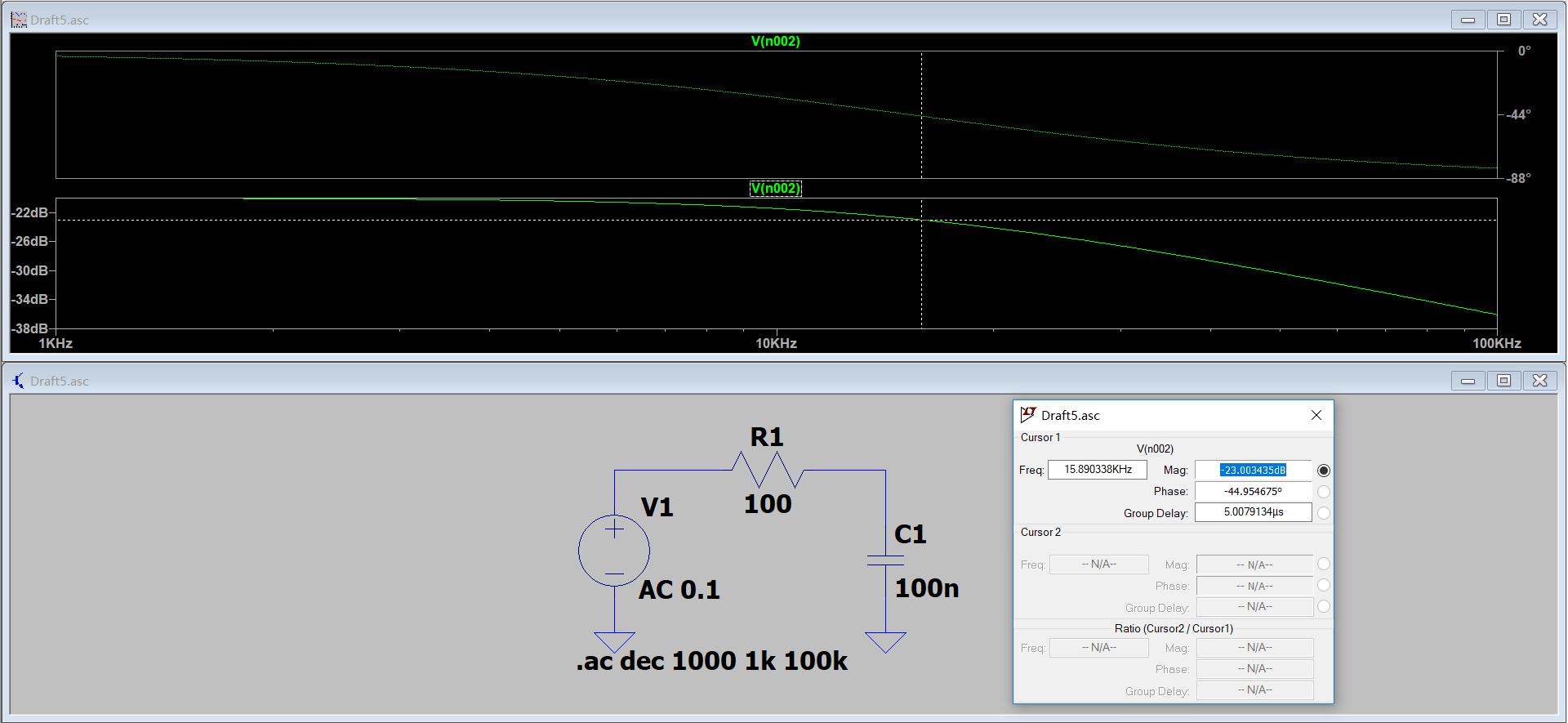
Digital first-order low pass filter Simulink Simulation
Digital first-order low pass filter Simulink Simulation
principle
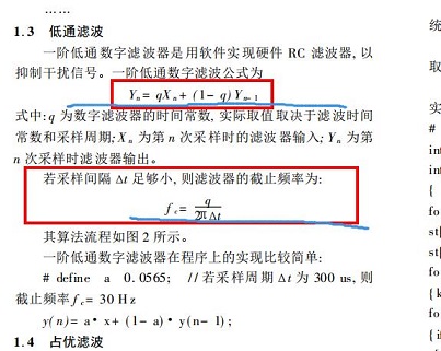
Procedure formula
y(n) = q*x(n) + (1-q)*y(n-1)
Where Y (n) represents the current output, X (n) represents the current input, Y (n-1) means the last output, Q is the filter coefficient.
Link: SeeDetailed analysis of digital first-order low pass filter.
Filter coefficient calculation method
q < F2π*t
Where Q is the filter coefficient (usually less than 1), f is the cutoff frequency, and T is the calculation frequency.
Link: SeeSoftware implementation and related parameters of RC first-order low pass filter.
But when the actual application finds that the method calculated by the method is smaller.
simulation
Construction according to formula
The main part is as follows, the cutoff frequency is calculated according to the RC circuit:
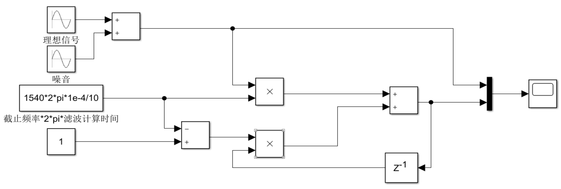
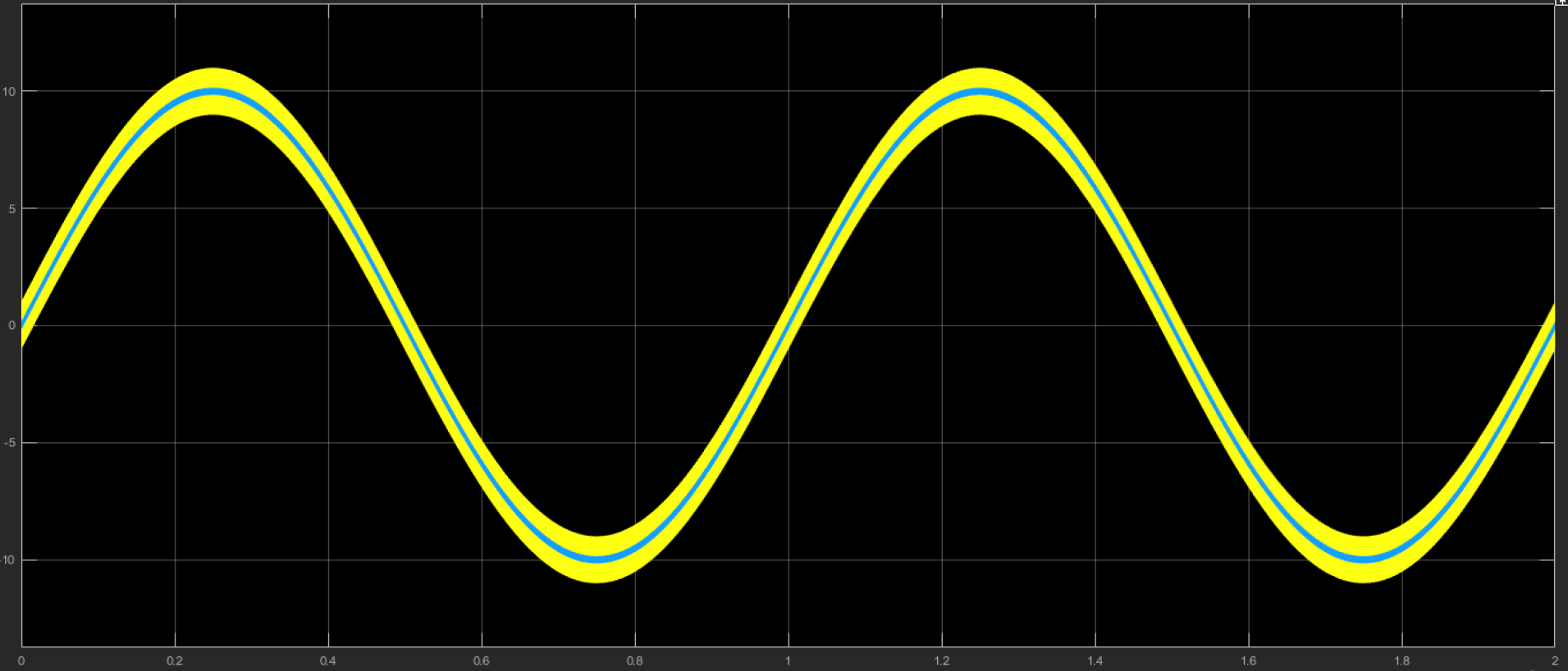
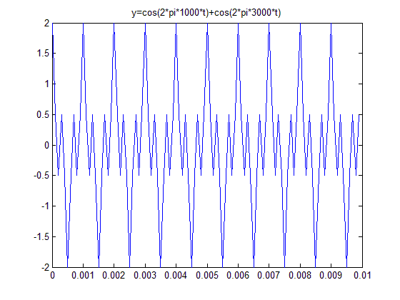
The ideal signal is a sine wave, the magnitude 10, and the frequency is 1 Hz. The noise is a sine wave, the magnitude 1, 10 kHz. as the picture shows:

The delay module sampling frequency is 10 kHz, which is set to 1e-4 (corresponding to a PWM triggering ADC sample of 10 kHz).
The model emulation is set to a fixed step 1e-6, and the simulation time is 2s.
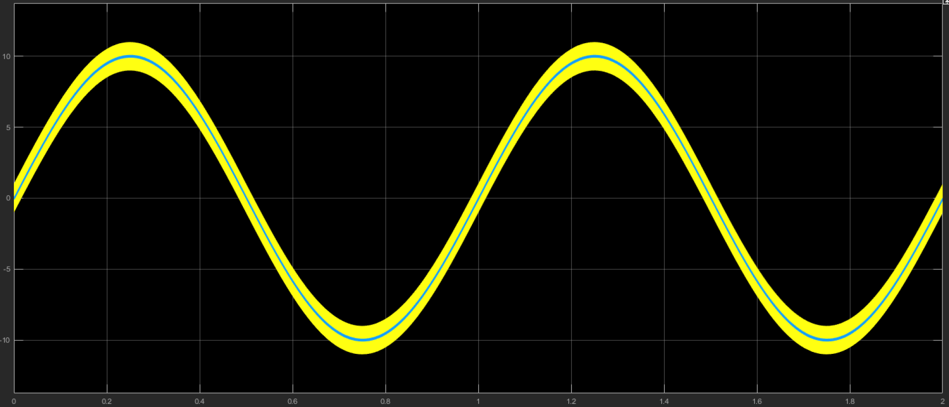
The output is as follows:
Use Simulink self-contained model
The main parts are as follows:
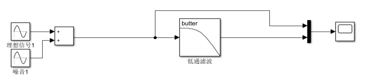
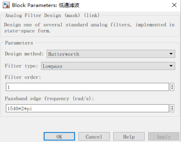
The low-pass filter cutoff frequency is 1540 Hz, and the specific setting is as follows:
Other settings are the same.
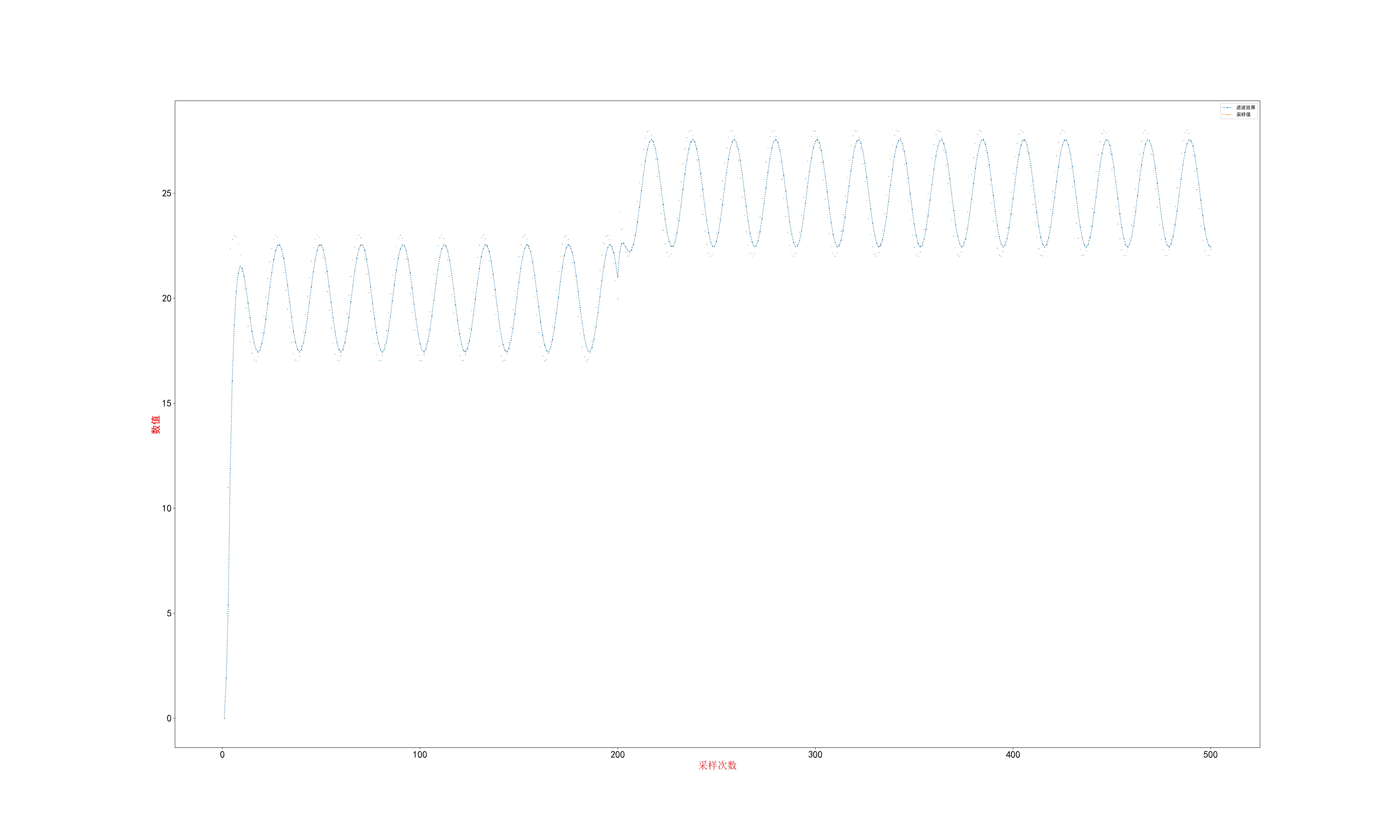
The output is as follows:
Intelligent Recommendation
First-order RC low-pass filter
table of Contents Calculation process Code Filter effect Calculation process Code Filter effect...
Digital bipolar low-pass filter - second order Badworth filter
Double pole low pass filter 1 description 1 description I recently saw the Apollo filter code, and I didn't understand it, so I would like to derive formula. code show as below It can be seen from the...
Digital first-order low-pass filter detailed analysis ice three-point water
Digital first-order low-pass filter detailed analysis Author: Ice Drops Original content, please indicate the source of the repost: http://blog.csdn.net/u013608300/article/details/78814693 The cause o...

Algorithm implementation of first-order RC filter (low-pass and high-pass)
Currently, the project needs to process signals. The target signal is a signal within a specific frequency range. High frequency is regarded as interference. The first-order RC filter is easy to imple...
More Recommendation

Second-order low-pass active filter design and simulation test
Preface In addition to useful information, the measurement signals output by the sensor often contain a lot of noise and other signals that are not related to the measurement, which affects the measur...
Understanding the transfer function of a first-order low-pass filter
The content of the principle of automatic control is very deep and needs to be learned gradually Algorithm implementation of first-order RC filter (low-pass and high-pass) Understanding the transfer f...
Mathematical Model and Algorithm for First-order RC Low Pass Filter Realization
Mathematical Model and Algorithm for First-order RC Low Pass Filter Realization 1. Successful domain mathematical model of a first-order RC low pass filter 1.1 Derivation of mathematical model 1.2 fre...
The simple application of first -order low -pass filter in STM32
First of all, look at the simplest first -order low -pass filter circuit model: It is not difficult to launch its transmission function: TF is related to the frequency of the filter, but the ac...
Butterworth Digital Low Pass Filter
There are many ways to realize signal filtering in matlab. This article uses the filter function. First, the numerator and denominator polynomials of the digital filter are generated from the butter f...