GPS Clock Module Timer and Synchronous Clock, 1PPS
tags: IMU and RTK and time synchronization system
GPS satellite
GPS satellite uses atomic clock ( atomic clock, is a timing device, accuracy can reach 1 second per 20 million years, consisting of receiving board, , phase-locked circuit, frequency division circuit, etc.)
GPS receiver
The GPS receiver on the clock module of the GPS receiver is responsible for receiving the RF signal transmitted by the GPS antenna, and then performs signal processing such as variable frequency demodulation, providing a 1PPS signal to the base station to synchronize.
Output:
- Frequency signals, 1PPS signals, and time code information.
- External frequency input and external second signal input.
Timer and synchronization clock
The GPS clock is mainly divided into two categories.
- A class is a GPS tense, mainly output time standard information, including 1PPS and TOD information;
- One class is a GPS synchronous clock, the latter outputs high stable frequency information that uses satellite signals to tame OCXO or clock, and a more stable time standard signal of local recovery.
GPS PPS Signal (PPS: Pulse Per Second)
NS level
The high-precision 1PPS signal output from the module is better than 50 ns, the duty cycle is 50%, and the 1PPS signal rises is a time synchronization point, and the rising edge is less than 5 ns. The first frame serial port message information and the 1PPS signal synchronization accuracy are about 36 ms. as the picture shows:
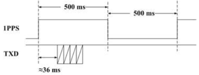
The 1PPS signal provides an accurate clock synchronization signal with a pulse width of 200-300ms, and the rising edge is performed, and the rise time Δt does not exceed 10ns.
The NMEA Time Data Information contains the time information corresponding to the current 1PPS rising edge, starting to transfer after 1pps rising edge, and pass it within 500ms.
For the Ublox F9P module, the UART outputs NEMA data, and the other GPIO outputs 1PPS pulse, there is a timing chart:

NMEA information
-
Nema includes time information, usually a second level, and some of milliseconds
-
1PPS is output per second, and the time is triggered as an example (without painting falling edge), the time is noteded in the figure, and the time to receive and process 1PPS pulse is also in the NS level.
-
Because Nema is sent and received by serial port, and once the amount of NEMA data has a KB level size, the processing time is far longer than 1PPs.
-
High-precision time synchronization can be achieved by the second time and 1PPs pulse in NEMA, high-precision time synchronization (NS level: responsive time according to 1PPs)
1, protocol format

 The NMEA-0183 protocol uses the ASCII code to deliver information, we call it a frame.

 The frame format is as follows: $ AACCC, DDD, DDD, ..., DDD * HH
\x0d\x0a

 Ø "$" - frame command starting position

 Ø AA (identifier symbol) CCC (statement name) - address domain

 Ø DDD ... DDD - Data

 Ø "*" - checksum prefix

 Ø HH - checksum, all character ASCII code between the $ with *

 (All bytes are different or the operation, after the checksum is received, the 16-en-format ASCII characters are converted.)

 Ø CR LF carries and wraps

 General TOD packets generally support: G P R m C, GPRMC, GPRMC, GPZDA input and output, format as follows:

 3.1 $ GPRMC statement

 3.1.1 frame format

$GPRMC,<1>,<2>,<3>,<4>,<5>,<6>,<7>,<8>,<9>,<10>,<11>,<12>*<13>

         UTC (Coordinated Universal Time) Time, HHMMSS.MS (Time Second. Mix) Format

         Positioning state, A = effective positioning, v = invalid positioning

         Reserve

         Reserve

         Reserve

         Reserve

         Reserve

         Reserve

         Reserve

         UTC date, DDMMYY (Sun Moon Year) format

         Reserve

         Reserve

         Check and verify

 3.1.2 Example

 Message: $ GPRMC, 083550.00, A, 200919, A * 57

 1) 083550.00 Meaning: The current UTC time is 8: 35: 50.00

 2) a meaning: current status is effective

 10) 200919 Meaning: September 19, 20th

 3.2 $ gpzda statement

 3.2.1 frame format

$GPZDA,<1>,<2>,<3>,<4>,<5>,<6>*<7>

         UTC (Coordinated Universal Time) Time, HHMMSS.MS (Time Second. Mix) Format

         UTC date, DD (day)

         UTC date, mm (month)

         UTC date, yy (year)

         Reserve

         Reserve

         Check and verify

 3.2.2 Example

 Packets: $ GPZDA, 083550.00, 20, 09, 19, 100, 00 * 57

 1) 083550.00 Meaning: The current UTC time is 8: 35: 50.00

 2) 20 Meaning: The current UTC date is 20 days

 3) 09 Meaning: The current UTC date is September

 4) 19 Meaning: The current UTC date is 19 years

 However, in practice, since the end of the TOD information is lagged behind the rising edge of the PPS, it should pay attention to the correspondence between second pulse and time information.
Intelligent Recommendation

Synchronous clock, asynchronous clock----concept analysis
Table of contents synchronous clock asynchronous clock clock constraint grouping Phase Synchronization, Frequency Synchronization phase synchronization frequency synchronization In-phase clocks, homol...
Write clock with timer
You can see the small clocks written with timers on the page. Today we will simply implement such small functions: What you need to notice when implementing the clock is: 1. When you get the month, yo...

Make a clock with a timer
Make a clock with a timer My idea is to use newData to get the current time, and then use the timer to call myself. Constantly get the current time to achieve the effect of dynamic display time. Here ...

Digital clock and timer
The role of the timer The timer is turned setInterval interval type 2000ms interval is 2s to pop up once a. setTimeout delay type The difference between the two timers: One is on every 2s will ...
More Recommendation
A timer (2) of the digital clock
To create a useful digital clock quest to obtain first time system, then the separate hours, minutes, seconds out, then with Polygon drawing, then a timer TIMER is displayed together with the second, ...

stm32-- Timer - Clock source
/** @defgroup TIM_Master_Mode_Selection TIM Master Mode Selection * @{ */ #define TIM_TRGO_RESET 0x00000000U #define TIM_TRGO_ENABLE ...

Timer (3) mechanical clock
Get current time Let's look at the structure of SYSTEMTIME Let's take a look at the mechanical clock, it's cool How can there be no renderings: A little knowledge of trigonometric functions is needed ...
Clock effect (timer)
JavaScript time object: var myTime = new Date();// Current time (the time object of the system when the computer reads this code) The detailed time obtained on this object isNumber type: MyTime.getFul...
Timer (alarm clock) design
1. Create the MyTimerTask class, define two variables, run time runAtTime and task target; 2. Initialize the time and task in the construction method, the time is the incoming time parameter + the cur...