Detailed Explanation of Crystal Oscillator - Pierce Oscillator
tags: circuit design Pierce oscillator crystal oscillator
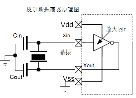
1. Definition:
Pierce oscillator (Pierce oscillator): It is an electronic oscillating circuit, which is suitable for generating oscillating signals with a quartz oscillating crystal.
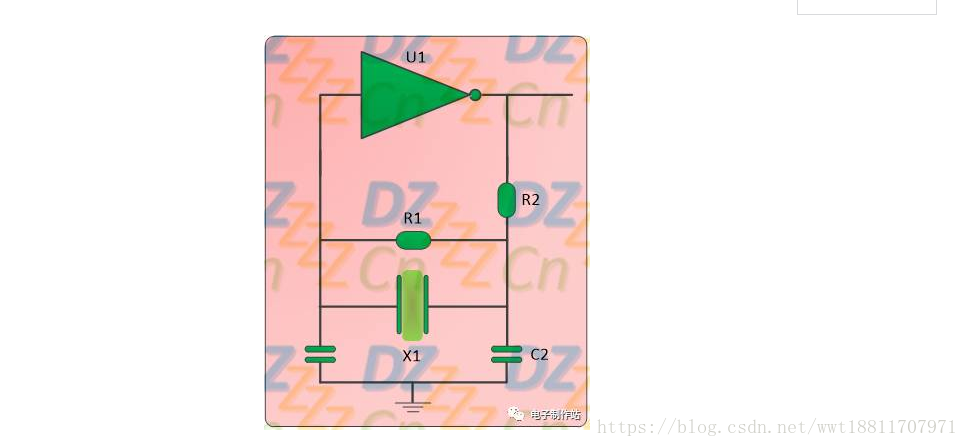
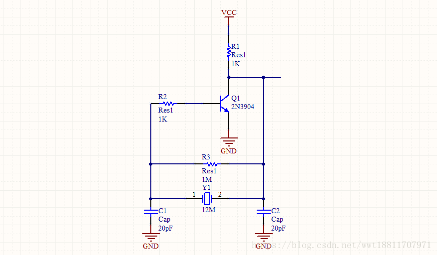
R1 in the above figure is the feedback resistor (generally ≥1MΩ), which makes the inverter in the linear working area at the beginning of the oscillation. R2 is an isolation resistor, which isolates the output from the pi network. This resistor causes a little extra phase shift with C2. The role of this resistor is to suppress high-frequency mixed oscillation to obtain a clean output signal; to reduce the driving power of the quartz crystal to prevent exceeding the allowable driving power of the quartz crystal.
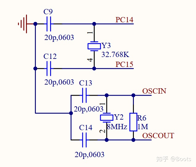
Almost all digital circuits that use quartz crystals to oscillate to generate clock signals now use Pierce oscillators. It consists of an inverter, a resistor, a quartz crystal, and two capacitors. For the crystal oscillator circuit of our commonly used IC, an inverter and a resistor are basically built-in, and only one crystal oscillator and two resistors are needed. As shown below:
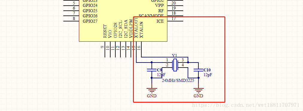
C9 and C10 in the above figure are external capacitors connected across, which are determined by the load capacitance.
Load capacitance CL (Load capacitance), which is the total effective capacitance across the two ends of the crystal in the circuit (not the external matching capacitance of the crystal oscillator), mainly affects the load resonance frequency and equivalent load resonance resistance, and determines the oscillator circuit together with the crystal. Operating frequency, by adjusting the load capacitance, the operating frequency of the oscillator can be fine-tuned to the nominal value.
- working principle
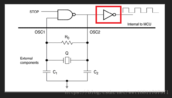
For an oscillating circuit, there must be positive feedback, and the closed-loop gain must be greater than 1. Resistor R0 causes negative feedback, which increases the open-loop gain requirement of the amplifier. R0 is usually as large as possible to minimize feedback and overcome current leakage at power-up. When using 1MHz and 20MHz crystals, R0 should be in the range of 1MΩ to 10MΩ. For ceramic resonators, R0 is generally 1MΩ.
As shown in the figure above, the quartz crystal and two resistors form a π-type bandpass filter network, which provides a phase shift and voltage gain of 180° at approximately the resonant frequency of the quartz crystal. At the frequency of oscillation, the quartz crystal is inductive and can be regarded as an inductor with a high Q value. The 180-degree phase shift of the π-type network and the negative gain of the inverter combine to form a positive loop gain (positive feedback), which makes the bias voltage set by the built-in resistor unstable and oscillates.
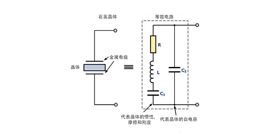
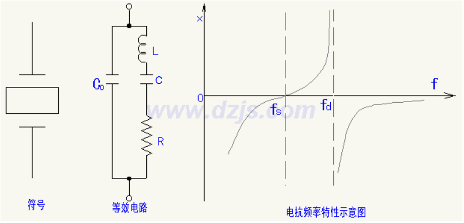
The resonator Q and the capacitors C1 and C2 form a resonance loop. C1, C2 represent the external capacitance and any parallel parasitic capacitance. Crystal and ceramic resonators have small-signal equivalent circuits, as shown in the following diagram:
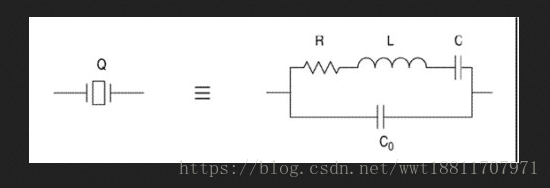
R is the series resistor, L and C are the starting or series inductors, and capacitor C0 is the shunt capacitor representing the sum of the low frequency shunt capacitance of the resonator and parasitic capacitance in the crystal box. Any additional parasitic capacitance between the OSC1 and OSC2 pins is included in this value.
Simple built Pierce oscillating circuit:
———
Copyright statement: This article is an original article of CSDN blogger, following the CC 4.0 BY-SA copyright agreement, please attach the original source link and this statement for reprinting. Original link:"Pierce Oscillator"
Intelligent Recommendation
How crystal oscillator works
Crystal or Jingzhen, or silly? Crystal is short for crystal resonator (Crystal), also known asPassive crystal. Generally, it is an electronic component that uses the piezoelectric effect of quartz cry...
The working principle of crystal oscillator
Crystal or crystal, or is it silly to distinguish? Crystal is the abbreviation of crystal resonator (Crystal), also known asPassive crystal. Generally, it is an electronic component that uses the piez...
Types of crystal oscillator
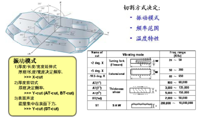
Cutting method The main frequency characteristics of a crystal oscillator depend on its internal crystal unit. The characteristics of the crystal unit depend on the cutting process. Different cutting ...
STM32 circuit crystal oscillator
The crystal oscillator is composed of a quartz crystal. The reason why a quartz crystal can be used as an oscillator is based on its piezoelectric effect: adding an electric field to the two poles of ...
Crystal Oscillator Circuit
Crystal oscillator circuit and working principle crystal oscillatoris an electronic oscillator circuit for the mechanical resonance of a vibrating cryst...
More Recommendation
The role of microcontroller crystal oscillator
Crystal oscillator, also known as crystal oscillator, is usually divided into two types: active crystal oscillator and passive crystal oscillator. Passive crystal oscillator is generally called crysta...
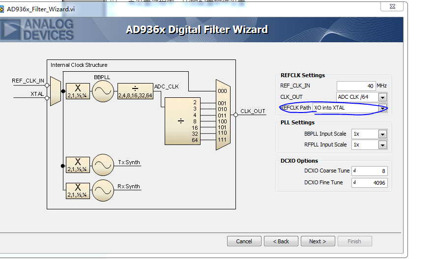
AD9361 crystal oscillator crystal selection
When actually using the AD9361, sometimes the hardware circuit design has two options for the reference crystal, one is crystal and the other is crystal During the setup process, such as configuring s...
Clock circuit crystal and crystal oscillator
Overview In digital circuits, both data transmission and reception require a clock as a reference. Data can be sampled on the rising edge of the clock, the falling edge, or both the rising and falling...
Introduction to crystal/crystal oscillator circuit
1. Introduction to crystal oscillation circuit Crystal oscillators can be divided into two categories: parallel resonance and series resonance. One type is that crystals are used as equivalent inducto...
The difference and use of crystal crystal and osilator crystal oscillator
Problem description: The use of MCU, MPU, and CPU is inseparable from the problem of crystal oscillator, because PLL needs to be used, crystal oscillator is equivalent to the heartbeat of MCU. I have ...