Zero crossing detection
tags: Electronic hardware foundation
AC-220V zero point detection
The general system structure is as shown in the figure below.
Zero-crossing detection has three main functions:
(1) SCR trigger. By detecting the AC220V zero-crossing point, the conduction time of the thyristor can be adjusted to performVoltage controlWait.
(2) Relay protection. When using a relay to control the on and off of AC220v, if the relay is closed near the peak of AC220v, a large spark will be generated, which will affect the life of the relay and cause various electromagnetic interference. If it is closed at the zero-crossing point of AC220v, the impact will be reduced. .
(3) Timing. AC220v frequency is 50Hz, cycle is 20ms. After full-wave rectification, an interrupt is generated at each zero point, which can be timed in units of 10ms.
Design principle:
The principle diagram of zero-crossing detection is shown in the figure. AC220v is reduced to AC 9v through a transformer, and then full-wave rectified. The rectified signal can be directly used for zero-crossing detection. The filter capacitor c1 can be used for other purposes by connecting the follow-up circuit such as 7805. Diode D1 is used to isolate the rectifier and filter parts, maintain the waveform at Zero, and provide a signal source for zero-crossing detection.
Obtain the sampled signal at Zero, then divide the voltage with two 10K resistors, and then connect the triode to the voltage. The triode works in switching mode. When the base voltage Vbe≥0.7V, the triode is turned on and outputs a low level to PB4; on the contrary, the triode works in an off state and outputs a high level to PB4. The corresponding relationship between the sampling signal at Zero and the input signal of PB4 is shown in Figure 2-2. Use the rising edge of PB4 to generate a 10ms external interrupt, and each time an interrupt is generated, it is the zero point of AC220v.
This example uses 6 LEDs as a display. The LED display is refreshed every time a zero-crossing interrupt is generated. The LED refresh frequency is as follows:
LED0 50HZ flashes for 10ms, lights up, 10ms off, lights up and goes out in sync with the power zero point
LED1 25HZ flashes for 20ms, lights up, 20ms off, lights up and goes out synchronously with the power zero point
LED2 12.5HZ flashes for 40ms, lights up, 40ms off, lights up and goes out in sync with the power zero point
LED3 6.25HZ flashes for 80ms, lights up, 80ms off, lights up and goes out in sync with the power zero point
LED4 3.125HZ flashes for 160ms, lights up, 160ms off, lights up and goes out in sync with the power zero point
LED5 1.5625HZ flashes for 320ms, lights up, 320ms off, lights up and goes out in sync with the power zero point
Zero-crossing detection principle diagram
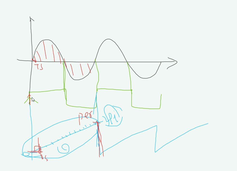
Time error between zero-crossing interrupt generation and actual AC220v zero point
As shown in the figure above, when the voltage drops to 0.7V, the PB4 port gets a rising edge and an interrupt is generated. There is a time difference between the interrupted ground and the true zero point. This time difference is related to the output voltage of the transformer and the resistance divider at the front end of the transistor. In this circuit, the theoretical calculation formula of the time difference between interrupt generation and zero point is:
0.7=4.5√2 *sin(w * t)
where 4.5√2 is obtained by dividing the voltage peak value 9√2 through two 10k resistors
w=2*3.14* f (f is 50Hz)
After calculation, t=350us.
Actually measured by the oscilloscope, the time difference between interrupt generation and zero point is about 500us.
There are many zero-crossing detection schemes for alternating current, and the most common scheme I used before is shown in Figure 1:
Figure 1 AC optocoupler zero-crossing detection circuit
The circuit of Figure 1 can detect the time when the alternating current passes through zero, but it has many drawbacks, which are listed as follows:
- The resistance consumes too much power and generates more heat. 220V alternating current, calculated according to the effective value of three 47K resistors, the average power of each resistor is 220^2/(3*47k)/3=114.42mw. For 0805 chip resistors, calculated according to the power of 1/8w, the current power consumption is close to its rated power, and the resistor generates a lot of heat. At the same time, it should be noted that the effective value of the mains power is 220V, and its peak voltage is 311V. Based on this calculation, we can get the instantaneous maximum power of each resistor as 228mw, which seriously exceeds the rated power of the resistor, so it is dangerous to use.
- The zero-crossing reaction speed of the optocoupler is slow, and the rising edge time of TZA is long. The actual test found that the transition time of the rising edge and falling edge of the optocoupler zero-crossing point is about 120us (the high and low voltage difference is 3.3V). It is acceptable for general applications, but the response time for synchronous applications in communication will seriously affect communication quality. Because it can be considered that a zero-crossing event has occurred within 120us, that is to say, my judgment of zero-crossing may have a deviation of up to 120us.
- According to the conduction characteristics of the optocoupler, the zero point of the circuit indicates the zero point that lags behind the actual alternating current. The lag time can be calculated based on the conduction current of the optocoupler. The typical value of NEC2501 is 10ma. In fact, the optocoupler is generally turned on when the forward current reaches 1ma. Now calculate with 1ma current, the resistance is 3×47k=141k, then the voltage is 141V, and the corresponding lag time is about 1.5ms. Assuming that 0.5ma turns on, the voltage is 70V, and the lag time is 722us.
- The optocoupler conduction time is longer, that is, the gradual process of optocoupler current from 0 to conduction current is longer, which leads to obvious difference in the edge time of optocoupler characteristics and poor product consistency. Assuming that 1ma is used as the conduction current of the optocoupler, it takes 1.5ms to change the 220v alternating current from 0V to 141V. Due to the consistency problem during the period, some optocouplers may be turned on at 0.5ma, and some may be turned on at 0.7ma. Now suppose that the lowest conduction current brought by the consistency is 0.5ma, then the corresponding conduction voltage is 71V, and the corresponding lag zero time is 736us, which shows that the zero difference between different optocouplers may reach 764us! (In the actual test, I tested 10 samples, of which the time difference between the two optocouplers' conduction performance was the biggest up to 50us, and the others were generally around 10us). This creates a lot of trouble for different devices to use the circuit to synchronize.
- Limited by the conduction current of the optocoupler, the AC signal amplitude range that this circuit can detect is narrow. Calculated at 1ma, this optocoupler can only detect signals with AC signal amplitude greater than 141V. If the signal is used for synchronization, then the synchronization signal will not be obtained when the device is under low voltage testing.
- The TZA output waveform is quite different from the standard square wave, and the duty cycle is higher than 50%. The time error of the duty cycle in the actual test reaches 1.2ms, and the time difference cannot be ignored in the application.
Based on the various problems listed above, the synchronization quality using the alternating current zero-crossing point is poor and needs to be improved. The first solution I thought of was to use the comparison function of the comparator to generate a standard square wave. The comparator outputs a high level during the positive half cycle of the alternating current, and the comparator outputs a low level during the negative half cycle of the alternating current. The time error of this scheme only depends on the response speed of the comparator level transition and the comparator's differential level resolution. Take lm319 as an example, the maximum bias voltage is 10mv, the comparative sensitivity is 5mv, and the response time of 5V output level transition is within 300ns, plus asin(10e-3/311)/2//pi/50 = 100ns. The difference between the two is about 400ns in total, which is much lower than the scheme shown in Figure 1. In practical applications, I used LM358 instead of the comparator. Its bias current is 50na, and a 1M resistor is connected in series. The voltage that satisfies the bias current is 50na×1M=50mv. According to st-lm358 data, its open-loop frequency response can reach 100db at 1k, so theoretically the input level of 1mv can still be recognized. Compared with the previous assumption, take 50mv, asin(50mv/311)/2/pi/50 = 500ns, the SR of the amplifier is 0.6V/us, assuming that the conversion to 4V requires 7us. Therefore, the absolute error of using LM358 is 7.5us, and in fact, due to the commonality of each device, the deviation in synchronization should be less than 1.5us.
After the plan is finalized, the circuit design should be carried out. Many problems were encountered during the actual circuit debugging, which is now recorded here for future reference. The main problems include:
- For the lack of basic understanding of the differential op amp circuit, I initially considered using a resistor divider circuit. According to the maximum voltage of 311V, the resistor divider is 1:100. A 2M resistor is used to connect a 20k in series, and the voltage across 20k is taken. The theoretical maximum difference is 3.11V. The circuit is shown in Figure 2-1. The circuit eventually ended in failure. After studying and finding the reason, it is because there is no reliable working point, or there is no unified reference ground, floating input cannot be amplified. For this same reason, the circuit shown in Figure 2-2 found on the Internet also ended in failure.
- In order to provide a unified reference for the differential amplifier circuit, Figure 2-2 is finally modified, and a large resistor is drawn from the + and-ends of the differential input to the "ground" of the test system, because it is a single power amplifier that takes into account LM358 The common mode input signal range is 0-VCC-1.5V. Due to diode limiting, the voltage across the diode is up to 0.7V, and because the neutral level is connected to the ground, the voltage range of the positive and negative input to the ground is -0.35 To +0.35. The final circuit is shown in Figure 3, which can realize the design function.
Summary of experience:
- Understanding the common-mode input range of an operational amplifier is very important to the design of an operational amplifier circuit. If the input signal exceeds the common-mode voltage range, the amplifier will not work properly.
- Any signal coupling needs to be driven by current. The current limit of the amplifier and the "ground" connection between different devices are not as large as possible. When the circuit in Figure 3 was originally designed, when R2 and R3 were initially set at 500K, the differential voltage between the test ground and R2 and R3 was tested simultaneously with dual channels of an oscilloscope, showing that it has the same waveform with an amplitude of about 8V. Theoretically, the amplitude of the waveform at both ends of the original R2 and R3 should be 0.35V, and the phase is opposite. After repeated experiments, it is found that the reason is that the current of R2 and R3 is too small to achieve the effect of common "ground". The test waveform of reducing the resistance of R2 and R3 is consistent with the theory.
- In order to safely test the voltage waveform of the 220V terminal, I consulted the relevant information of the floating test technology. At the same time, it has been experimentally verified that the common ground of the oscilloscope and the system under test must be disconnected in the floating test. Specifically, the test instrument and the platform under test do not have the same reference ground potential, so that the ground of the oscilloscope probe is shorted to the ground There will be no accidents on the test platform. Take this experiment as an example, suppose we need to measure the real-time waveform of the utility power, how to measure it. We can test this way. When the oscilloscope is powered, the three-core plug is only connected to the L and N terminals, and the ground is not connected. In this way, the ground clamp can be clamped to one end of the mains, and the probe can be used to measure the waveform at the other end. Of course, it is better to connect a large resistance in series with the grounding clamp to one end of the mains, and the probe should also connect a large resistance in series to the other end of the mains. What are the consequences if you do not test this way? ? ? If you don’t test this way, because the ground clip of the oscilloscope probe is connected to the ground wire of the three-core plug, removing the live wire or neutral wire through the ground clip is equivalent to connecting the live wire or neutral wire directly to the earth. It's okay, if it is a live wire, it must be a short circuit! very dangerous! ! !
——Transfer from 21IC Community
http://bbs.21ic.com/icview-1714198-1-1.html
Intelligent Recommendation
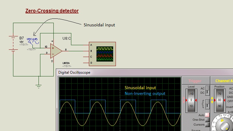
Proteus Tutorial - Zero Crossing Detector
Op amps as zero crossing detectors Sine voltage signals are usually converted into square waves using zero crossing detectors. In this circuit, the op amp operates in open-loop comparator mode. The po...
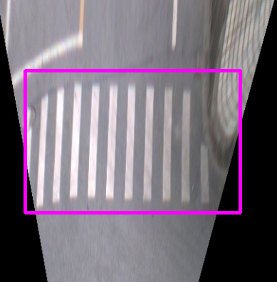
Zebra crossing detection based on OpenCV
The two programs test the video and picture data respectively, and the algorithm parameters are the same (there is no corresponding parameter to filter lane lines in the video, but because the zebra c...
Single-phase zero-crossing phase-locked (PLL)
Single-phase phase-locking generally uses zero-crossing phase-locking The voltage is judged by the hardware circuit. The previous time is less than 0, and the latter time is greater than 0. It is judg...
TCP zero window detection
The TCP zero window detection is used to obtain the window update message that triggers the opposite end to prevent the infinite loop caused by the loss of the window update message. It also helps the...
More Recommendation
Short-time zero-crossing rate in time domain for acoustic event recognition
1. Introduction to the concept The short-term zero-crossing rate can be regarded as a simple measure of the signal frequency and is a rough estimate of the spectral characteristics. (1) Zero crossing ...

Short-term average zero-crossing rate test based on MATLAB and Python
1. Demand analysis Using five basic waveforms to detect the short-term average zero-crossing rate algorithm. Generate a 5s waveform with a sampling frequency of 8000Hz: 1. Sine wave: Ampli...

Analysis of short-term average zero-crossing rate based on MATLAB and Python
The MATLAB implementation of short-term average zero-crossing rateAnother blogIt has already been introduced here. Here mainly introduces the short-term average zero-crossing rate of the s...

Time domain characteristics of speech signal (2) Zero crossing number
Introduction to Zero Crossing Zero-crossing analysis is a commonly used method to estimate the frequency of a speech signal. The speech signal is a wideband signal. For a continuous signal, the wavefo...

20210211 plecs diode rectifier diode rectifier zero crossing error
According to the error message, the algorithm should be changed to nonadaptive, so refer to the setting of the diode rectification routine in the blockset version Give up, 10,000 errors But after refe...