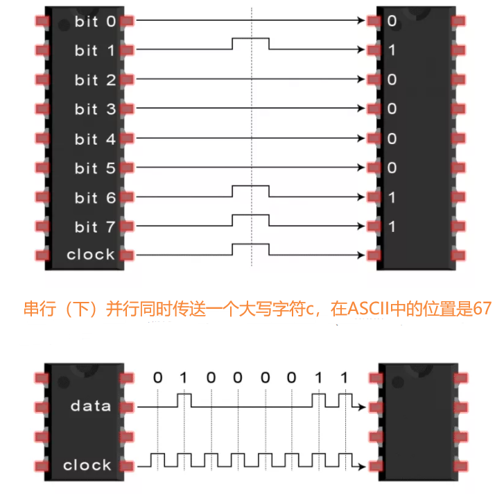
SPI, I2C, UART and other communication protocols
tags: STM32 Single -chip machine Embedded hardware
SPI, I2C, UART and other communication protocols
1. SPI
SPI (Serial Peripheral Interface) is a synchronous serial transmission specification launched by Motorola, the United States, and a single -chip microcontrol serial communication interface that is more commonly used now. This interface is a high -speed, full -time, and synchronized communication bus.
SPI Master Cong Mode
SPI is divided into two modes, one SPI communication system is usually a main device, one or more of the device. The main device provides clocks, and the device that receives the clock is from SLAVE (SLAVE). When there are multiple devices, they are managed through their own film selection signals. SPI is a full -duplex and no definition speed limit. The speed is generally set by the maximum clock frequency that the host or the clock can support.
SPI signal line
SPI interfaces generally use four signal line communication: MOSI, MISO, SCK, CS
- MOSI: The main device output/input from the device. The pin sends data in the main mode and receives data in the mode.
- MISO: Main device input/output from the device. The pin sends data from mode and receives data in the main mode.
- SCK: Serial clock signal, generated by the main device.
- CS: Selected signals from the device film, controlled by the main device. Its function is to be used as a "selection pin", that is, select the specified slave device. Generally, low levels are effective.
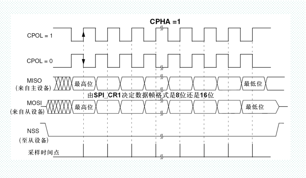
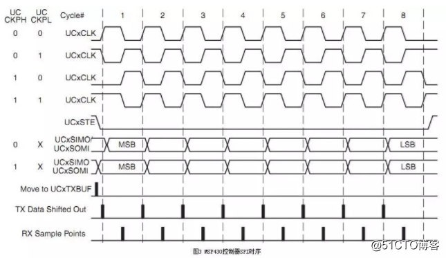
Four modes of SPI communication
The SPI CLK line is not defined, so it can be set freely. The clock polar (CPOL) and the clock phase (CPHA) can be combined into four different modes.
Clock polarity (CPOL) defines the clock free status level:
- CPOL = 0 means that when the SCK is free, it is low level
- CPOL = 1, indicates that when the SCK is free, it is a high level
Clock phase (CPHA) definition data collection time points:
- CPHA = 0, data sampling at the first jumping edge of the clock
- CPHA = 1, data sampling in the second jump along the clock
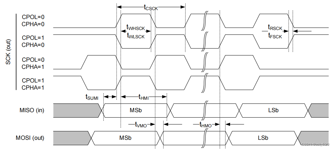
The main setting mode of the main machine should be consistent, and the SPI can be set to be sent with low bytes or high bytes.
SPI advantages and disadvantages
The advantage of SPI communication
- Full dual -working serial communication
- High -speed data transmission rate
shortcoming
- No hardware from machine response signal
- More pins are needed (connecting multiple lines from the device to choose multiple cables)
2. I2C
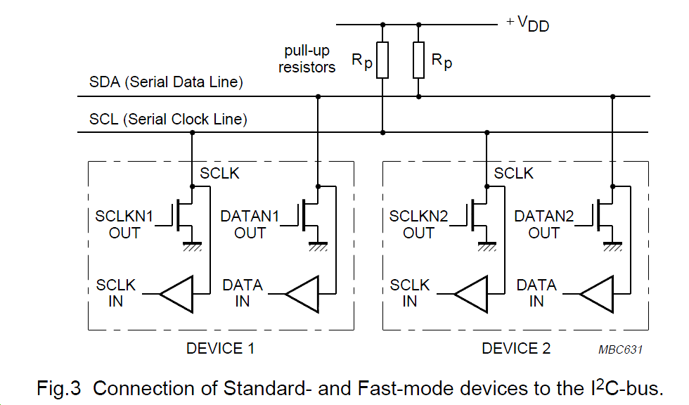
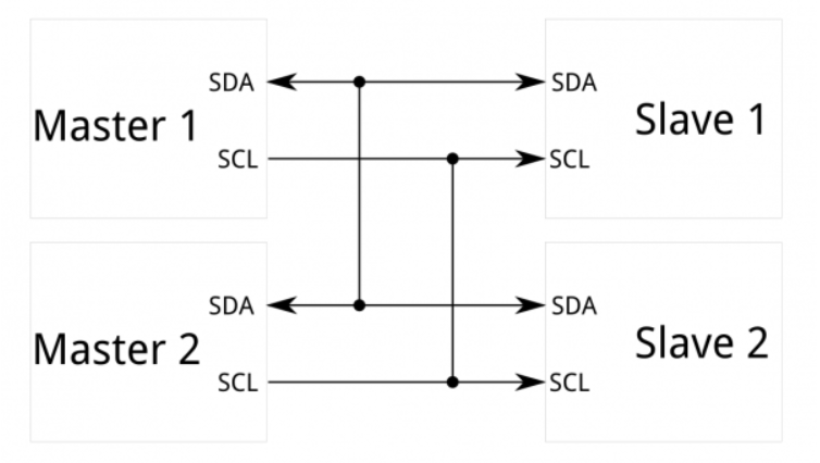
The I2C bus is a serial and half -dual -tool bus launched by Philips. It is mainly used for communication between close -range, low -speed chips; IIC bus has two two -way signal lines. The data cable SDA is used for receiving data. The clock line SCL is used to synchronize the clock of the two parties. The hardware structure of the IIC bus is simple, the cost is low, and it is also a relatively common serial peripheral interface.
The IIC bus is a multi -host bus. The device connected to the IIC bus is divided into hosts and slaves. The standard communication rate is generally 100kbps and 400kbps at high speeds
The I2C host has the right to initiate and end a communication, and the console can only be called by the host. When there are multiple hosts on the bus at the same time, the I2C also has the function of conflict detection and tailoring to prevent errors from being generated. Each connection is connected to The devices on the I2C bus have a unique address (7bit), and each device can be used as a host or as a console (only one host at the same time). Work, the device that I2C bus sends the data on the bus when communicating is the transmitter, and the device that receives the data is the receiver.
I2C bus communication process:
- The host sends the start signal enable bus
- The host sends the slave address and read and write positions
- Subscribed from the phone sending signal signal responding to the host
- The host sends a byte data
- The receiver sends a response signal response to the sender
- Cycle steps 4, 5
- After the communication is completed, the host sends a stop signal release bus
After sending the start signal, the host must first send a byte of data. The high 7 -bit of the data is the address of the slave, and the lowest bit indicates the transmission direction of the subsequent byte. After receiving data, after all the boards received the byte data on the bus, these 7 addresses compared with their own addresses. If the same, it is considered to be found by the console, and then the eighth place is determined to be The transmitter or a receiver.
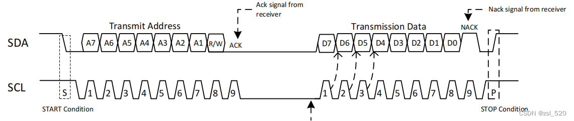
Start signal and stop signal
- Start starting signal: SCL is high -electricity, SDA, from high changes to represent the start signal
- STOP stop signal: SCL is high -electricity, SDA means stop signal from low to high
The start signal and stop signal are issued by the host. After the initial signal is generated, the bus is in a state of occupation.
Byte transmission and response
- Each byte is 8 -bit in length when I2C bus communication, when the data is transmitted,First transmit the highest bits, and then transmit low positionAfter the transmitter is sent, the receiver must send a one -bit response to respond to the transmitter, that is, there are 9 bits in a frame.
Synchronous signal
- When the i2C bus is transmitted, the clock line SCL sends a data to the data line to the data line during the low level. During this period, the signal on the data line allows changes. Reading a data on the data cable. During this period, the signal on the data cable does not allow changes and must be stable.
The SCL SDA cable of I2C is generally a leakage state and requires an external pull -up resistance.
I2C advantages and disadvantages
Advantage
- You can drive multiple devices with only two lines
shortcoming
- Low transmission rate
3. UART
Universal Asynchronous Receiver Transmitter is the universal asynchronous receiver, which is a general serial and asynchronous communication bus. The bus has two data cables, which can be sent and received for all -dual -workers. Generally called serial communication
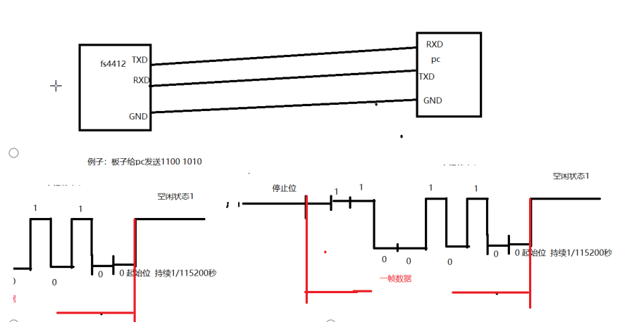
UART hardware connection
TX: Data send interface
RX: Data receiving interface
The two devices are connected to the RX between the two devices, and the RX and TX can work normally. Pay attention
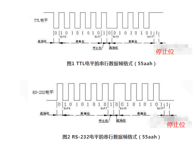
UART frame format
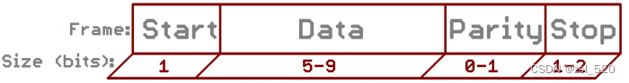
The composition of a frame of data: starting position + data bit + verification position + stop bit
-
Starting position: 1 bit, logic '0', indicating the beginning of transmission of a character
-
Data bit: The data to be sent is generally 5-9 bits, and 8-bit commonly used
-
Verification digits: 0 ~ 1, no verification/strange verification/occasional verification
-
Strange verification: When there are strange logic in the data bit '1', this bit is 0, otherwise it is 1
-
Puppet verification: When there are occasional logic ‘1’ in the data bit, this bit is 0, otherwise it is 1
-
Stop bit: It means the end of the transmission of a character, which can be 1, 1.5, 2 high levels
-
Free position: When the current line is not transmitted, it is a high level
-
Sequence of data transmission:First transmit the data of the data first, and then transfer the high position of the data
Communication speed (Potter rate): In the application of single -chip microcomputers, the common communication speed is 9600, 19200, 57600, 115200 bit/s
UART advantages and disadvantages
Advantage
- Simple structure
shortcoming
- Poor anti -interference ability (the clock needs to be consistent)
- The communication distance is very short
4. SPI, I2C, UART, etc.
As the most commonly used serial communication interface in single -chip microcomputer. Since it can be widely used in major systems, there are applicable application scenarios. Choose different interfaces according to the needs of different projects.
Intelligent Recommendation
ARM --------> Day 5, UART communication, I2C and SPI
1.uart communication ------>Asynchronous serial communication Asynchronous: random, no clock line Synchronization: Time Clock Single work: A-> B Half duplex: A-> B or B-> a Full duplex: A-...
The difference between SPI, UART, and I2C communication
:https://mp.weixin.qq.com/s?__biz=MzUxMjEyNDgyNw==&mid=2247498262&idx=1&sn=c7d106299976104394e4ce682682747f&chksm=f96b88e2ce1c01f4bddec93439ee8c0adbdb63f5a4afc105ea03ab0a58ba3d48445965...
The difference between SPI, I2C and UART three serial bus protocols
I2C (Inter-Integrated Circuit) bus concept: I2C communicationOnly 2 bidirectional buses are needed- A data line SDA (serial data), a clock line SCL (serial clock). The SDA line is used to transmit dat...
[Note 2] STM32 SPI, and differences are summarized I2C, UART three kinds of serial communication protocols (I2S audio bus otherwise noted)
SPI: SPI (Serial Peripheral Interface) serial peripheral interface, full-duplex, synchronous serial 1, SPI bus consists of three signal lines: a serial clock (SCLK), serial data output (SDO), a serial...
SPI, I2C, and UART
First, SPI SPI (Serial Peripheral Interface) is a synchronous serial data transmission standard proposed by Motorola. It is widely used in many devices. interface The SPI interface is often referred t...
More Recommendation
SPI、I2C、UART、CAN
First, the introduction 1. SPI SPI (Serial Peripheral Interface) is a synchronous serial data transmission standard proposed by Motorola, which is widely used in many devices. interface The SPI interf...

spi, i2c, uart difference
SPI, IIC, UART difference The first difference is of course the name: SPI (Serial Peripheral Interface: Serial Peripheral Interface); I2C(INTER IC BUS) UART (Universal Asynchr...
UART, I2C and SPI comparison
1 UART, I2C and SPI comparison UART I2C SPI English name Universal Asynchronous Receiver/Transmitter Inter-Integrated Circuit Serial Peripheral Interface Chinese name Universal asynchronous transceive...
Introduction to UART, SPI and I2C
Article Directory 0 Several concepts 1 UART 2 SPI 2.1 SPI signal line 2.2 SPI transmission data mode (timing) 3 I2C 3.1 Idle state 3.2 Start bit and stop bit 3.3 Validity of data 0 Several concepts Tr...
UART/I2C/SPI
This article focuses on the difference and contact of the three communication interfaces of the UART / I2C / SPI, helping to understand these three interfaces, after understanding, whether it is using...