CAN Bus Error Analysis and Resolution
From
CAN Bus Error Analysis and Resolution
background
Writing this article is because I see online article on CAN bus error handling, all-are born to move or copy the contents of the textbook data files, especially in the domestic hard to find some valuable content, which makes some really people need very upset, including myself. This does not intend to do further study on the CAN error handling mechanism, but the specific problems encountered in the practical work to analyze some of the common mistakes and solutions CAN bus.
CAN node processes data transceiver
Learn CAN transceiver process node on the data bus is important, before an article explaining some error handling CAN bus, but those are the things in theory, if not in-depth understanding of data on the CAN bus transceiver process, understand what the theory is inevitable that some of those obscure.
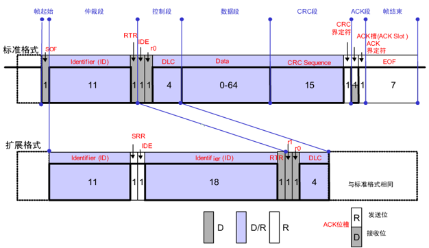
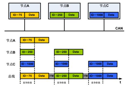
At the same time we know each node on the CAN bus to send data to the bus can simultaneously read data on the bus, and the data transmitted by itself for comparison.
CAN message has been successfully within this gap, the receiving node may respond to the setup information, the response field is filled with the dominant 0, that is when sending a recessive response procedure may be as follows: When the ACK information is transmitted to the front when Del, the information may be considered have been transferred, the receiving node also receives sufficient information to detect the received information is correct, so when the receiving node will detect the signal is correct, if correct, ACK will set bit dominant 0, Note that this time, since the transmitting node and the receiving node in turn is still transmitting the ACK information is set to 1, it will be detected when read back the ACK is 0, it is judged successful reception. Note: the receiving node which has a cover with a dominant recessive bit ACK --- covering process, covering the readback +.
Adding a respective longitudinal Del ACK, the time error is to be considered, so that the receiving node has enough time to confirm the ACK. This process is described, CAN is a two-way interactive transmission process, the transmission side transmitting node, while the node to confirm the data correctly recovered, and the receiving node also receives the time and at the right time an ACK is set to 1.
CAN bus error
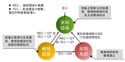
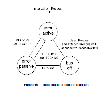
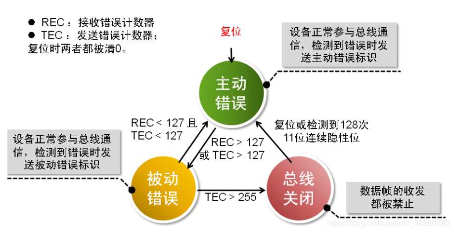
CAN bus error respectively transmit and receive error count, the count will have CAN BUS OFF after a certain accumulated, indicating that appear on the CAN bus serious mistake. FIG mechanism follows the state transition CAN bus error occurs:
If BUS OFF appeared, nodes on the bus need to do some action, such as restarting or the CAN controller on again, but these are just some of the remedies, the most fundamental is the need to find the root cause of BUS OFF.
Some tools and documentation CAN bus analysis:
- CANAnalyzer or logic analyzer
- Digital oscilloscopes
- Related softwaredebugtool
- CANController chip data sheet, which is very important
- Hardware circuit
- CANProtocol document
- Relevant versionLinuxKernel source
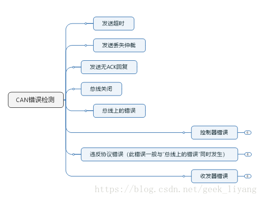
CAN node sends the wrong unsuccessful
Problem Description and analysis
Mounted on the CAN bus of a node to transmit data on the bus is not successful, logic analyzer can not see any waveform. PS: This should be the most pit father thing I came across a. The following specific look at how unsuccessful. So debug interrupt status register to view CAN_STATUS That CAN display 0xE5, view the CPU data sheet:
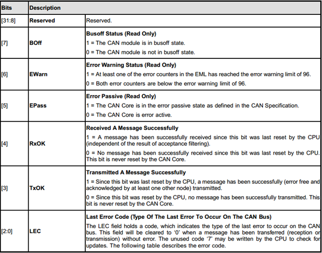
CAN bus BUS OFF state directly into the state, it means that the error count has overrun check transceiver error count registers CPU transceiver transmits display TEC error count reaches 248, the reception error count is 0; This is evident, the data has not even transmitted to bus.
See further register value i.e. LEC last LAST ERROR CODE error code is displayed BIT0 ERROR:
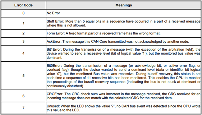
See table above error codes found, i.e. BIT0 error during the data transmission, although the CAN node wants to send a dominant bit device, i.e. a logic 0, but at the same time listening to the CAN bus data bits on the bus as recessive bits, i.e., a logical 1. This means that the data sent to the CAN core on the first bus had been wrong, are they not transfer data to the CAN bus through CAN transceiver.
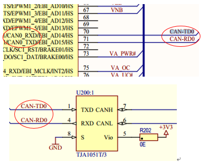
I plant and I have never met have been using this and other wonders of the CAN bus, but because it is so new CPU development issues at the same time is also suspected hardware troubleshooting software problems, but after a while the investigation found no software The problem. Go back and analyze hardware, and after a while tracing investigation, found that the transceiver line CAN transceiver line CPU and CAN transceiver gas reversed, direct collapse (PS: Hardware Brother you can not pit brother):
to sum up
CAN node unsuccessful data transmission, analyzes the CAN controller is not the problem itself, see the CAN Core CPU status register, analyze whether there BUS OFF, if present BUS OFF, the specific error check, is active error or passive wrong, there is no overrun send error count, error status once the last of what is happening, to see a bit stuffing error, or formatting errors and other errors, then analyze specific issues. This is typically caused by a hardware error transmission line problems, such as a light barrier nonconductive secondary side, the transmission interface such as poor contact, wonderful Furthermore some errors, for example according to the present embodiment, the transceiver cable directly connected backwards pit father ah!
CAN node of the Socket CAN error frame is detected
Problem Description
We see the following CAN Socket log in three error frame within 38 seconds, but did not cause BUS OFF bus, indicating detected on the bus to the wrong, there may have been interference, there may be data sent too dense lead the bus overload, but an error occurs in the 38 seconds, but has returned to normal period.


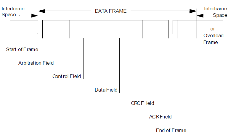
CAN ID: 0x20000004 = 10 0000 0000 0000 0000 0000 0000 0100, i.e., the value of the arbitration field.
Linux kernel source code analysis
Because this error is that I plant CAN controller CPU TI's AM3352, kernel versionLinux 3.2.0
So we CAN kernel error can_id defined by the core point of view:
- /* error class (mask) in can_id */
- #define CAN_ERR_TX_TIMEOUT 0x00000001U /* TX timeout (by netdevice driver) */
- #define CAN_ERR_LOSTARB 0x00000002U /* lost arbitration / data[0] */
- #define CAN_ERR_CRTL 0x00000004U /* controller problems / data[1] */
- #define CAN_ERR_PROT 0x00000008U /* protocol violations / data[2..3] */
- #define CAN_ERR_TRX 0x00000010U /* transceiver status / data[4] */
- #define CAN_ERR_ACK 0x00000020U /* received no ACK on transmission */
- #define CAN_ERR_BUSOFF 0x00000040U /* bus off */
- #define CAN_ERR_BUSERROR 0x00000080U /* bus error (may flood!) */
- #define CAN_ERR_RESTARTED 0x00000100U /* controller restarted */
Frame error by the CAN ID: 0x20000004 = 10 0000 0000 0000 0000 0000 0000 0100Removal of up to 1 (SOFZ start bit?), Because the quorum is 29-bit, so it should be0 0000 0000 0000 0000 0000 0000 0100 =0x00000004, neither CAN_ERR_BUSOFF nor CAN_ERR_BUSERROR, but CAN_ERR_CTRL, i.e. CAN controller problems, and we look at the data [1] CAN controller error type description Description:
- /* error status of CAN-controller / data[1] */
- #define CAN_ERR_CRTL_UNSPEC 0x00 /* unspecified */
- #define CAN_ERR_CRTL_RX_OVERFLOW 0x01 /* RX buffer overflow */
- #define CAN_ERR_CRTL_TX_OVERFLOW 0x02 /* TX buffer overflow */
- #define CAN_ERR_CRTL_RX_WARNING 0x04 /* reached warning level for RX errors */
- #define CAN_ERR_CRTL_TX_WARNING 0x08 /* reached warning level for TX errors */
- #define CAN_ERR_CRTL_RX_PASSIVE 0x10 /* reached error passive status RX */
- #define CAN_ERR_CRTL_TX_PASSIVE 0x20 /* reached error passive status TX */
Display data [1] = 0x04, as shown below we look at our intercepted packet error frame data:

That specific error is:
#define CAN_ERR_CRTL_RX_WARNING 0x04 /* reached warning level for RX errors */
That CAN controller receives the error count reached the level of warning, Be warned, if you go on like this CAN controller will overload, and even cause BUS OFF bus.
Let's return to the kernel source for this error handling: generating data [1] = CAN_ERR_CRTL_RX_WARNING error sources kernel function:
- static int ti_hecc_error(struct net_device *ndev, int int_status,
- int err_status)
- static int ti_hecc_error(struct net_device *ndev, int int_status,
- int err_status)
HECC is referred to as TI High Speed CAN controller terminal, with the error handling function of the above described TI CAN Core below, we can see that is received CAN controller error count is greater than when the REC 96 kernel will report this error
- if (int_status & HECC_CANGIF_WLIF) { /* warning level int */
- if ((int_status & HECC_CANGIF_BOIF) == 0) {
- priv->can.state = CAN_STATE_ERROR_WARNING;
- ++priv->can.can_stats.error_warning;
- cf->can_id |= CAN_ERR_CRTL;
- if (hecc_read(priv, HECC_CANTEC) > 96)
- cf->data[1] |= CAN_ERR_CRTL_TX_WARNING;
- if (hecc_read(priv, HECC_CANREC) > 96)
- cf->data[1] |= CAN_ERR_CRTL_RX_WARNING;
- }
- hecc_set_bit(priv, HECC_CANES, HECC_CANES_EW);
- dev_dbg(priv->ndev->dev.parent, "Error Warning interrupt\n");
- hecc_clear_bit(priv, HECC_CANMC, HECC_CANMC_CCR);
- }
to sum up
This error occurs because the warning is likely to be:
- thisCANOn the bus due to possible interferenceCANThe controller receives the error occurred,CANSignals on the bus through the transceiver into a differential signal level, then the signal susceptible to outside interference, so easy to makeCANThe controller receives an error occurs, the receiving error register receives the counts accumulated error will be reported to a certain value of this error, if the error count reaches a certain level even cause bus is offBUS OFF. If the final is due to the interference caused by the accumulated error count, then you should investigation the source of interference and increase anti-jamming measures.
-
thisCANNode still needs to receive a large amount of filtered message after message, resulting inCPUmiddleCANThe controller receives an error, and the error count has reached the upper limit false alarms. But the news is still not overloaded bus, the bus can also send and receive data properly, there is no causeBUS OFF. But for a safe and reliable control system, this warning is absolutely not allowed. We need some means to avoid such a problem, for example, reduce the amount of concurrent data bus, to reduce the bus load.
CAN bus devices offline and error recovery
This problem is also very strange, but it seems to be relatively common problem, the situation is such a problem is often more, such as CAN Power off section is electricity cut off, the bus will certainly see this heartbeat monitor CAN nodes many, or CAN bus node did not send a heartbeat, blocked tasking years, and this CAN node or a physical connection and disconnection bus, and other reasons.
A situation I want to say here is another problem I encountered factory.
Problem Description
After missing the entire system is restarted find one Cortex M0 device node on the CAN bus, and other equipment is the same M0ArchitectureMCU and the same equipment control software is not the case of the missing appear.
To be continued.
Intelligent Recommendation
CAN bus error handling and fault confinement
Complex environment often hear the phrase "all with the car CAN bus, the bus that stability should be safeguarded" and that guarantee this stability precisely because CAN bus to face a field...

CAN bus introduction (four) --- error frame
Then the previous article "Introduction to CAN bus (4)-data frame and control frame 》 4.3.3 Error frame 4.3.3.1 Frame structure of error frame When sending and receiving messages, if a node on th...
Incisive CAN bus error handling and fault definition
We know that each node on the CAN bus will read the data on the bus at the same time when sending data to the bus, and compare it with the data sent by itself. — CAN arbitration??? Knowing the a...
[CAN] CAN BUS error detection and error status management
error detection The CAN controller shall provide the following error detection mechanisms. Bus monitoring (that is, monitoring the bus level by looping back to the RX PIN through the transceiver) bit ...
CAN bus physical layer analysis (3)
1. CAN topology network The devices connected to the CAN bus are called node devices (CAN Node), and the topology of the CAN network is generally linear. The most commonly used wiring harness is twist...
More Recommendation
CAN bus data link layer analysis (4)
In SPI communication, the four signals of chip select, clock signal, data input and data output have separate signal lines. CAN uses two differential signal lines and can only express one signal. The ...
Analysis of CAN bus-ACK response mechanism
1: Definition of answering field The length of the response field is 2 bits, including the response gap (ACK SLOT) and response delimiter (ACK DELIMITER). In the reply field, the sending station sends...

Dbc analysis application in CAN bus (C++ implementation)
"Do everything to know the destiny" February 3, 2020 The first blog after the Spring Festival I don't want to mention how bad and annoying the beginning of 2020 is Doing what you shou...
Application of CAN bus technology in ship data analysis
Application of CAN bus technology in ships The application of CAN in ships began in the early 1990s. In 1994, the German MTU company successfully developed the CAN-based MCS-51 monitoring system, crea...
A2L file analysis based on CAN bus (1)
Articles directory suggestion: Data area Record Layout FNC\_VALUES AXIS\_PTS\_X Numerical type: Axis: Calibration Characteristic Numerical calibration Simulink generates the calibration in A2L: The ca...