Tessent Atpg Series Chapter 8 Test Pattern Generation - ATPG Tool Pattern Types (sequential pattern concept)
Article Directory
This article introduces ATPG Tools pattern Types, the type of ATPG pattern, refer to ug:
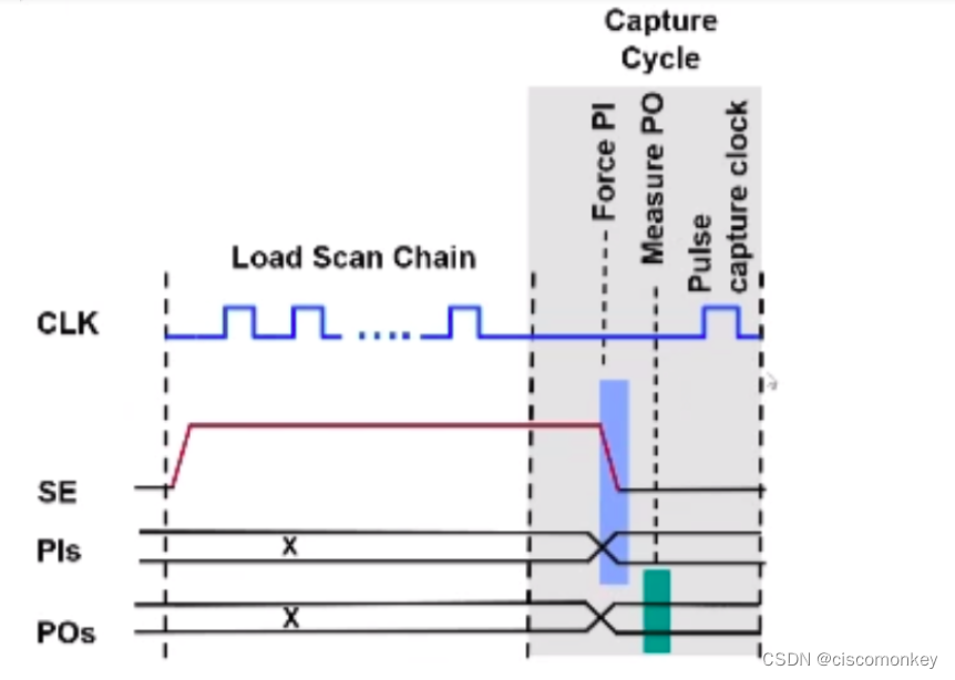
Basic Scan Patterns:
By default, the tool will generate a basic scan pattern. The basic scan pattern is to give a set of values to all scan cells (load in) and primary PI, and to observe on all primary output and scan cells (measure po) , the tool will use the default scan clock to capture data to observable scan cells(capture_clock_on,capture_clock_off). Each pattern is independent.
The basic pattern follows the following events:
1、load values into scan chains.
2. Force values on all non-clock primary inputs (with clocks off and constrained pins at their constrained valued)
3、measure all primary outputs(except those connected to scan clocks)
4、pulse a capture clock or apply seleced clock procedure.
5、unload values from scan chains
load in -->force PI–>measure PO–>capture—>load out
Clock PO Patterns
Clock Sequential Patterns
For sequential patterns, this is a very common pattern, but beginners often don't understand the behavior of this pattern very well.
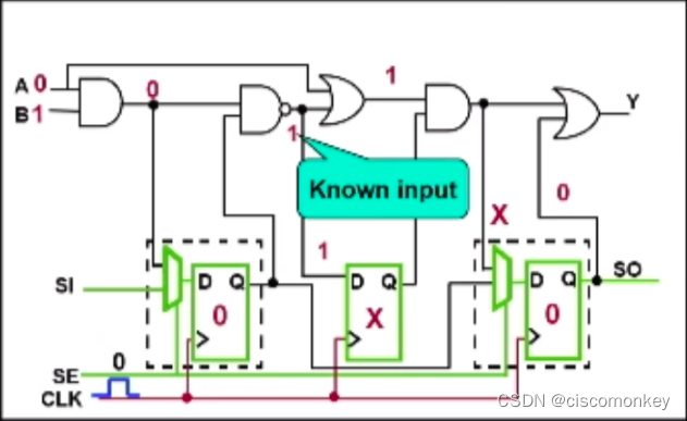
As shown in the figure below, we can see that there is a non-scan cell in the circuit, and the sequential pattern is to improve the coverage of the non-scan cell.
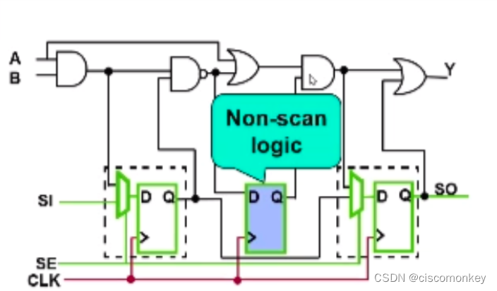
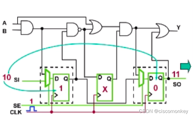
There is a non-scan cell in the above figure as the connection part of the combinational logic, then we know that the Q port of the non scan cell in the above figure cannot give a value, because load in will only load SDFF, at this time the Q of the two registers will have values, and then we will force PI , measure PO, and then load out is compared with Scan out, so in the capture clock, even if this non-scan cell captures a value other than X, when continuing to load out, it will only compare the value on scan out .
The events of the sequential pattern during testing include:
1、load scan chain
2、apply clock sequential cycle : Repeat force PI–> pulse clock N times, at this time N is the timing depth -1
3、apply capture cycle : force PI measure ,PO pulse ,capture clock
4、unload
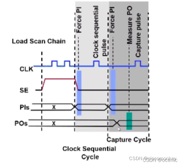
The tool will automatically identify the sequential depth element
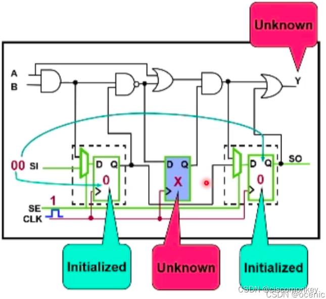
As shown in the figure above, we shift in to enter the value 00, and then perform force PI, but at this time we know that the non-scan cell is still in the X state. Even if I measure PO now, then my Y port is still unknown at the moment. Next, I will do the capture action, and then load out. At this time, I compare the value on the scan out chain. That is to say, the whole process affects my ratio to X because my non scan cell is X, thus affecting cov.
As shown in the figure above, enter the sequential cycle, pass the force PI, at this moment, the D port of the non scan cell will have a value.
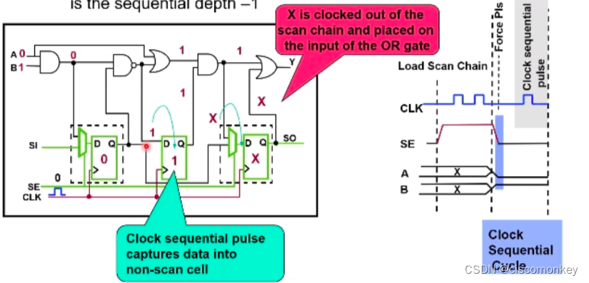
In the sequential cycle, play a sequential cycle. At this point, the non scan cell will capture the value. At this moment, the X value is transmitted to the D terminal of the last SDFF
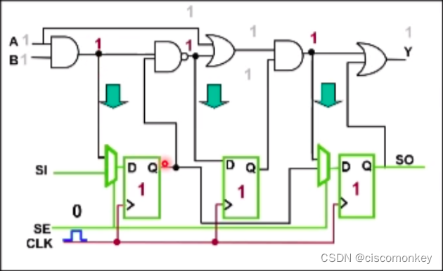
As shown in the figure above, the value of the non-scan cell is no longer X at this moment, and it already has a confirmed value. At this moment, we enter the apply capture clock again, perform force PI measure PO during the capture cycle, and give a capture pulse to capture the value in the logic into the scan chain.
So far, we force PI for the first time, then the sequential pulse is to pour the value into the non scan cell, and the second PI is the real value for capture.
As shown in the figure above, the captured value is loaded out.
This article explains very well, and I will repeat it again based on my understanding of this article. If the original CSDN blogger has any objections, please contact me.
Refer to high-quality articles
Intelligent Recommendation

PHP Design Pattern Series (8): Builder Pattern
Builder mode Builder Pattern: Separate the construction of a complex object from its representation, so that the same construction process can create different representations. The builder mode is to ...
Chapter 8 Factory Method pattern
A concept Factory method model, define an interface for creating an object, so decide which instance of a subclass of class, method of making factory to instantiate a class to delay its subclasses Two...

Chapter 8 "Factory Method Pattern"
1. Comparison of factory method and simple factory: 1.1. When adding new functions, the difference between the two: (1) Simple factory needs to complete work: add a new functional class + change facto...

4. DFT Advanced --ATPG
ATPG automatic test pattern generation 1. physical defects short and open drc escape It has the characteristics of diversity Good test, so the academic community proposed fault...
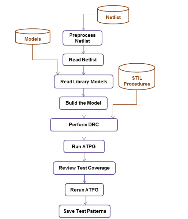
TMAXug ATPG Design Flow
Article catalog How to start TMAX running script This article blog introduces the TMAXUG series ATPG Design Flow ATPG Process is a process that generates a test vector that allows the ATE device to re...
More Recommendation

Template pattern of pattern series
One. Template pattern 1. Preliminary exploration of template method mode The template operation mode defines a unified framework in the algorithm, and delays some steps to be implemented in the subcla...
Singleton pattern of pattern series
One. Singleton mode Design pattern: It is a set of code design experience that has been used repeatedly and is known to most people. Purpose: The use of design patterns is to reusable code, make it ea...
Design pattern concept ----- with decorator pattern
The design pattern is mainly based on the following object-oriented design principles. Program the interface instead of the implementation. Prefer to use object composition rather than inheritance. Si...

Sequential pattern mining
Purpose: Learn sequential pattern mining to class Apriori example. 1.1 Introduction Apriori algorithm is a classical data mining frequent itemsets and association rules mining algorithm. A priori in L...

Application of C Language in Design Pattern-Appearance Pattern-Chapter 8
Introduction to Facade Appearance mode is also called facade mode The appearance mode is to provide a unified interface for accessing a group of interfaces in the subsystem. The appearance mode define...