Eleven OPUS coding of real -time audio compilation decoding
tags: Audio encoder Opus encoding
This article refuses to reprint any form, thank you.
Chapter 4 OPUS Code
OPUS is a relatively mature open source commercial voice codec. Its encoding quality is high and has no copyright usage fee. Because the WebRTC standard stipulates that the audio encoder is supported, the major browsers today support OPUS encoders. OPUS has many prominent advantages, such as low latency, wide encoding range, controlling the output bit rate. OPUS is often used in procedures such as real -time communication and real -time streaming media. It is usually accompanied by video streams. Because human ear is more sensitive to sounds, it is often used as the benchmark of audio streaming RTP timestamp as the benchmark video stream. Audio and video synchronization is no longer the scope of this book.
OPUS encoding the bit rate range from 6Kbps from narrowband to 510kbps with high -quality stereo. OPUS uses LP and MDCT technologies. It has achieved good compression rates and audio quality in voice and music scenarios. Among them, LP technology is based on Silk encoder. The MDCT technology is based on CELT encoder. The OPUS encoder is Silk and CELT. The integration of the encoder combines the advantages of Silk's voice coding with CELT's advantages in music coding. Through the method of mixed coding, it can obtain the best encoding quality in the voice and music scenario. The core of the OPUS encoder is Silk and Celt. The output Bit rate flow is the mix of Silk and CELT Bit flow. Silk and CELE The relationship between the two and OPUS is shown in Figure 4-1:

Figure 4-1 OPUS encoder structure box diagram
Because this book focuses on the principle of coding and its implementation, some logic control flows of the OPUS encoder are not specifically introduced. These control flows include the selection of encoder mode, encoding bit rate distribution, etc. The specification manual of the OPUS encoding is RFC6716. The specification defines the tissue format of the bittius. The steps of the Bi special flow decoding steps. How to obtain the parameter manual required by the decoding end does not make a compulsory requirement. Of course, the manual also gives a set of implementation methods for coding. Some of the methods based on deep learning can be improved in the aspects of packet loss compensation. The core of OPUS codec is based on the LP and MDCT algorithm. This book is based on the OPUS_DEMO.C example in the OPUS encoder open source project to explain the code implementation process and its code implementation.
4.1 Silk encoding
In order to facilitate simple, the test engineering code is based on the source code implemented by floating -point C languages. Some fixed -point skills are involved in the "Real -time Voice Treatment Practice Guide". OPUS_DEMO.C compiles OPUS_DEMO binary (because Xcode compiles the project, the project source see the author Github), the test program uses the following. The command line parameters analyze the OPUS encoding. The test command will be tested in this parameter that the OPUS will call SILK and Celt.
// Coding command parameters
//[-e] <application> <sampling rate (Hz)> <channels (1/2)> <bits per second>  [options] <input><output>
 -e voip 48000 1 64000 -cvbr -framesize 20 -complexity 10  -bandwidth FB -inbandfec -loss 10 -dtx   ~/Downloads/48k_mono.wav out.bit
 // Decoding command parameters
-d 48000 1 -loss 10 out.bit out.pcm
OPUS_DEMO can test the encoding or test decoding. According to different parameters, the -E indicates that only running encodes. VOIP indicates that the test scene is VOIP scene. In addition, there are Audio and low delay scenarios. Mesize 20 is the coding frame length. Specifying 20ms is a frame length encoding, and the internal is encoded in 5ms subframes. Therefore, there are four subframes. Complexity is the complexity parameter that affects the quality of the coding voice. The value range is [0, 10]. The code bandwidth specifies, as shown in Figure 4.1, the maximum sampling rate signal of the Silk part of the coding is 16kHz. If the signal of the sampling rate is more encoded, the CELT is encoded. InBandfec is used in the use of FEC in the band to resist network packet loss and jitter. A environmental sound bag is to save the transmission bandwidth, because the maximum sampling rate of SILK coding signal is 16kHz, so the test case uses the sampling rate signal test here. LOSS is an simulated packet loss parameter 10 means 10%of the packet loss.
During decoding, the -D indicates that only the decoding. VOIP, 16000, 1, and 24000 parameters are the same as the encoding.-LOSS means discarding 10%of the package when there is decoding. When the FEC and PLC are not tested, only the decodes of Silk and CELT can be used, because the analysis of FeC and PLC is involved. Therefore, it is also necessary to analyze its traditional signal processing implementation. The decoding signal is naked PCM data, without WAV header information, so you need to use AudaCity to import the original data to view the frequency domain signal.
The core framework of the Silk encoding is shown in Figure 4-2. The encoding parameters include LTP, LSF, Gain, and Noise Shaping and the incentive code. When the encoding parameters select the CVBR, the coding rate of the final output is fluctuated up and down in this specified encoding rate, and the bidding rate of LTP and LSFs is indispensable when the parameters are coded. Therefore, it can adjust the output coding bit rate in Gain and Noise Shaping. Below the analysis of each module in Figure 4-2 analyzes its principles and related code implementation.

Figure 4-2 OPUS encoder core framework
4.1.1 interval encoder
Range encoder (Range Encoder) is a bit rate packager. It is a type of entropy encoding. It does not involve human pronunciation models. The voice encoder based on deep learning modeling can also be used to reduce the transmission rate of the transmission. The purpose of compression, the interval encoding method used by OPUS is similar to the 1.3.6 section. When encoding, call the EC_ENC_INIT () function to initialize the state of the interval encoder. See the location of the calling position. For different encoding objects, OPUS uses three interval encoding methods to pack audio characteristics:
- The entropy coding symbol of the fixed probability uses EC_ENCODE () (ENTENC.C),
- 0 ∼ 2 M − 1 0 \sim2^M-1 0∼2M−1Use EC_ENC_UINT () or EC_ENC_BITS () encoding,
- 0 ∼ f t − 1 0 \sim ft-1 0∼ft−1The integer of the non -2 index is encoded in EC_ENC_UINT ().
The interval encoder uses the four -dollar group vector (VAL, RNG, Rem, EXT) internally. The Val is the lower limit of the current distance. The RNG is the current distance range. The output of Rem single byte buffer. EXT is the value of the number. Val and RNG are 32-bit unsigned integer values. Rem is byte value, less than 255 or -1. EXT is an unsigned integer with at least 11 bits. ( 0 , 2 3 1 , − 1 , 0 ) (0, 2^31, -1, 0) (0,231,−1,0)After encoding a sequence, the RNG value of the encoder will be equal to the decoder decoding the RNG value after the sequence, which can be used to detect whether errors occur during the code. There are no EXT and Rem fields in the decoder.
4.1.2 encoding process
The main functions involved in the OPUS encoding process are shown in Figure 4-3. The function involved in the core algorithm is the implementation function of the core algorithm of the Silk encoder. Other functions are pre-processing and mode related settings. This chapter focuses on the implementation of the core algorithm of the Silk encoder.

Figure 4-3 Silk encoding core flowchart
When setting the OPUS encoding parameters in the command line, these parameters will be passed to the Silk encoder. SILK sets the work parameters encoded by these parameters. These parameters coding the sampling rate, coding ratio, encoding complexity and other parameters. These parameters call the simk_encode_frame_fxx (). E_native () and Silk_encode () function settings are completed.
4.1.3 OPUS_ENCODE function
OPUS_ENCODE () function is the OPUS coding interface function called Opus_demo test program. The return value of this function is the encoding length of the byte. Limited to coding output bit rate, Analysis_frame_size is the length of encoding frames, and the address space pointed to the PCM is stored with 16 bit WAV data.
//opus_encoder.c
2222 opus_int32 opus_encode(OpusEncoder *st, const opus_int16 *pcm, int analysis_frame_size,
2223       unsigned char *data, opus_int32 max_data_bytes)
2224 {
// Select the appropriate frame length, the smallest frame is 2.5ms, that is, a maximum of 400 frames in 1 second, 200 frames/second corresponding to 5ms, push in order, the maximum frame length encoding of 120MS is 120ms.
// Because the coding frame selected by the 4.1 section is 20ms, it is a reasonable value, so the frame_size = 320 here
2230    frame_size = frame_size_select(analysis_frame_size, st->variable_duration, st->Fs);
 // Obtain coding frame length according to the frame_size_select, applying space, single -channel data can also be coded stereo, Channels can be set by encoding parameter settings
2236    ALLOC(in, frame_size*st->channels, float);
// Coded data The number of floating points is used. When the data comes in, the number of 16bit is fixed, and the point of the floating point is turned by point.
2238    for (i=0;i<frame_size*st->channels;i++)
2239       in[i] = (1.0f/32768)*pcm[i];
// in: The input of the floating -point format uses data, Frame_size: The frame length of the sampling point count, the data: the encoded byte order storage the
// max_data_bytes: The maximum length of the encoding byte order, LSB_DEPTH: Least Significant Bit minimum validity number of validity 16 16
// pcm: short audio data, analysis_frame_size: Analyze the frame length of 20ms, 320 points
// c1: 0 C2: -2, coding channel number st-> channels, downmix_int is the address of the sampling function,
// The last parameter indicates the floating point API
2240    ret = opus_encode_native(st, in, frame_size, data, max_data_bytes, 16,
2241                   pcm, analysis_frame_size, 0, -2, st->channels, downmix_int, 0);
4.1.4 opus_encode_native
This function pre -process the data based on the input parameters, calculate the coding bit rate, and call the corresponding SILK and CELT encoder to encode the sound. The main veins of the code are commented in the code.
//opus_encoder.c
// Out_Data_Bytes is set to MTU (Maximum Transmission Unit). MTU is the largest protocol data unit that can be transmitted by the data link layer. For Ethernet, the size of the IP datagram. The consideration of the MTU is that the packet is not packed when transmitted in Ethernet. This advantage is that the network jitter and packet loss treatment are more convenient.
1047 opus_int32 opus_encode_native(OpusEncoder *st, const opus_val16 *pcm, int frame_size,
1048                 unsigned char *data, opus_int32 out_data_bytes, int lsb_depth,
1049                 const void *analysis_pcm, opus_int32 analysis_size, int c1, int c2,
1050                 int analysis_channels, downmix_func downmix, int float_api)
1051 {
// 1276 is the sum of the maximum bit rate of TOC fields (a byte) and 1275 coding, of which 1275 corresponds to 510kbps. When encoding stereo MUSIC, the number of encoding bytes can be accounted for. For each encoding package, TOC must exist.
1092     max_data_bytes = IMIN(1276, out_data_bytes);

// The final result of the storage interval code is the same as the Range after the interval encoding is the same as the Range after decoding.
1094     st->rangeFinal = 0;
// Forced address offset, get Silk and Celt encoder State
1108     silk_enc = (char*)st+st->silk_enc_offset;
1109     celt_enc = (CELTEncoder*)((char*)st+st->celt_enc_offset);
 // If it is a low latency mode, such as the application scenarios such as games, at this time delay_compensation = 0 to reduce the delay, but this will bring the parameter estimation error than when the delay compensation is compensated.
1110     if (st->application == OPUS_APPLICATION_RESTRICTED_LOWDELAY)
1111        delay_compensation = 0;
1112     else
1113        delay_compensation = st->delay_compensation;
 // If Complexity is relatively large, analyze first, and the analysis content includes tone, voice, music probability, etc.;
 // For fixed points, the complexity is greater than or equal to 10 to enable this analysis, which helps reduce computing resource consumption.
1120 #ifdef FIXED_POINT
1121     if (st->silk_mode.complexity >= 10 && st->Fs>=16000)
1122 #else
1123     if (st->silk_mode.complexity >= 7 && st->Fs>=16000)
1124 #endif
1125     {
// Depending on the frame energy, determine whether it is a mute frame
1126        is_silence = is_digital_silence(pcm, frame_size, st->channels, lsb_depth);
// The results of the analysis are stored in the Analysis_info structure. Analysis_pcm is a SHORT type audio input data. Frame_size: 20ms, 16kHz, 320, 320
1129        run_analysis(&st->analysis, celt_mode, analysis_pcm, analysis_size, frame_size,
1130              c1, c2, analysis_channels, st->Fs,
1131              lsb_depth, downmix, &analysis_info);
1132
// Follow the peak of the signal, when the voice probability calculated at run_analysis () is less than the earthen limit dtx_activity_threshold,
// Compare the current frame (because Run_ANALYSIS is judged to be less than the voice limit, so the frame is regarded as a noise frame) and the peak ability tracked here,
// When the energy of the peak energy is greater than the energy of the current frame, it will be mandatory that it is still encoded according to the voice frame to avoid decreased the quality of voice frame coding caused by misjudgment
1134        if (!is_silence && analysis_info.activity_probability > DTX_ACTIVITY_THRESHOLD)
1135           st->peak_signal_energy = MAX32(MULT16_32_Q15(QCONST16(0.999f, 15), st->peak_signal_energy),
1136                 compute_frame_energy(pcm, frame_size, st->channels, st->arch));
1137     }
// Since the frame length is 20ms, Frame_rate = 50, max_data_bytes = 1276, here you can calculate the maximum coding bit rate
1287     max_rate = frame_rate*max_data_bytes*8;
1288
// Based on parameters such as Mode/Channel/Bandwidth, calculate the 20ms frame length bit rate
// The actual bit rate will be smaller than the 24,000 of the command line parameters. This is because the CBR and the complexity require some expenses
1290     equiv_rate = compute_equiv_rate(st->bitrate_bps, st->channels, st->Fs/frame_size,
1291           st->use_vbr, 0, st->silk_mode.complexity, st->silk_mode.packetLossPercentage);
// Calculate whether to encode LBRR frame
1544     st->silk_mode.LBRR_coded = decide_fec(st->silk_mode.useInBandFEC, st->silk_mode.packetLossPercentage,
1545           st->silk_mode.LBRR_coded, st->mode, &st->bandwidth, equiv_rate);
// Here is a byte that is reserved for the TOC field because after the coding is encoded, fill in the TOC field
1623     data += 1;
// Initialize the interval encoder, each frame is initialized, so that when there is a network packet loss and jitter, there will be no impact.
1625     ec_enc_init(&enc, data, max_data_bytes-1);

 // Determine the frequency of Qualcomm according to the voice or Music situation
1630     if (st->mode == MODE_CELT_ONLY)
1631        hp_freq_smth1 = silk_LSHIFT( silk_lin2log( VARIABLE_HP_MIN_CUTOFF_HZ ), 8 );
1632     else
1633        hp_freq_smth1 = ((silk_encoder*)silk_enc)->state_Fxx[0].sCmn.variable_HP_smth1_Q15;
1634
1635     st->variable_HP_smth2_Q15 = silk_SMLAWB( st->variable_HP_smth2_Q15,
1636           hp_freq_smth1 - st->variable_HP_smth2_Q15, SILK_FIX_CONST( VARIABLE_HP_SMTH_COEF2, 16 ) );
1637
// For voice conditions, Cutoff_Hz = 60Hz
1639     cutoff_Hz = silk_log2lin( silk_RSHIFT( st->variable_HP_smth2_Q15, 8 ) );

 // Perform pre -filtering according to the use mode. Music scene only removes DC; the judgment conditions here set VOIP in the command line parameters
1641     if (st->application == OPUS_APPLICATION_VOIP)
1642     {
 // For voice, signal below the dead frequency Cutoff_Hz is not lower than that frequency, so it can be CUTOFF.
  // But for the music scene, the frequency of musical instruments can be very low, just need to go to DC.
1643        hp_cutoff(pcm, cutoff_Hz, &pcm_buf[total_buffer*st->channels], st->hp_mem, frame_size, st->channels, st->Fs, st->arch);
1644     } else {
1645        dc_reject(pcm, 3, &pcm_buf[total_buffer*st->channels], st->hp_mem, frame_size, st->channels, st->Fs);
1646     }
   // SHORT type PCM data storage first address PCM_SILK
    // frame_size: 320 16kHz 20ms frame length
    // nbyte: the number of bytes encoded
    // Activity: Whether the voice exists or not
1833         ret = silk_Encode( silk_enc, &st->silk_mode, pcm_silk, frame_size, &enc, &nBytes, 0, activity );
 // Because this section is only silk encoded, the CELT encoding after SILK has skipped the relevant code here
// Based on Silk_enCode results, generate TOC fields
2117     data--;
2118     data[0] = gen_toc(st->mode, st->Fs/frame_size, curr_bandwidth, st->stream_channels);
4.1.5 run_analysis function
In the case of high encoding complexity, based on the original audio analysis sound, voice probability, and music probability, the analysis content is stored in the following structure:
 //celt.h
 55 typedef struct {
 56    int valid;
 57    float tonality;
 58    float tonality_slope;
 59    float noisiness;
 60    float activity;
 61    float music_prob;
 62    float music_prob_min;
 63    float music_prob_max;
 64    int   bandwidth;
 65    float activity_probability;
 66    float max_pitch_ratio;
 67    / * Store in Q6 to save storage space */
 68    unsigned char leak_boost[LEAK_BANDS];
 69 } AnalysisInfo;
The run_analysis function mainly calls the tonality_analysis function to complete the relevant parameter calculation.
//analysis.c
// Tone analysis C: It is the number of channels
971          tonality_analysis(analysis, celt_mode, analysis_pcm, IMIN(Fs/50, pcm_len), offset, c1, c2, C, lsb_depth, downmix);


446 static void tonality_analysis(TonalityAnalysisState *tonal, const CELTMode *celt_mode, const void *x, int len, int offset, int c1, int c2,     int C, int lsb_depth, downmix_func downmix)
447 {

504     if (tonal->Fs == 48000)
505     {
 // Tone analysis is based on 24KHz, so the 48kHz input signal needs to be divided by two
507        len/= 2;
508        offset /= 2;
509     } else if (tonal->Fs == 16000) {
 // Use 24KHz analysis inside, so Len changes from 320 to 480
510        len = 3*len/2;
511        offset = 3*offset/2;
512     }
//mdct.kfft=] is 480 points FFT, that is
514     kfft = celt_mode->mdct.kfft[0];

// x: is input data
// Tonal-> INMEM size is 30ms @24KHz, where the offset tonal-> mem_fill = 240, which is equivalent to 10ms. This offset address will store data after weight sampling
// imin (len, analysis_buf_size-tonal-> mem_fill): 480, is the offset value
// Offset = 0, C1: 0, C2: -2, C: Channel number 1, C1 and C2 effects heavy sampling. For 16kHz, single channel data, you can ignore the two parameters of C1 and C2
//tonal->Fs:16000
// For the 16KHz input signal, the re-sampling algorithm is directly used to insert the same value directly, and then sampled the samples of 16KHz-> 48kHz ---> 24KHz to the heavy sampling.
// But the original 16KHz signal makes us only have signals below 8kHz here, so it has no effect
515     tonal->hp_ener_accum += (float)downmix_and_resample(downmix, x,
516           &tonal->inmem[tonal->mem_fill], tonal->downmix_state,
517           IMIN(len, ANALYSIS_BUF_SIZE-tonal->mem_fill), offset, c1, c2, C, tonal->Fs);
// Tonal-> Info's size is Hong Detect_size = 100, recycling
526     info = &tonal->info[tonal->write_pos++];
527     if (tonal->write_pos>=DETECT_SIZE)
528        tonal->write_pos-=DETECT_SIZE;
// Based on the difference between the maximum and minimum value of one frame, determine whether it is a mute frame
530     is_silence = is_digital_silence32(tonal->inmem, ANALYSIS_BUF_SIZE, 1, lsb_depth);
// 480 points @24KHz, 20ms; 240 points @24KHz, 10ms 10ms
532     ALLOC(in, 480, kiss_fft_cpx);
533     ALLOC(out, 480, kiss_fft_cpx);
534     ALLOC(tonality, 240, float);
535     ALLOC(noisiness, 240, float);
// Senate the signal after the sampling samples according to the requirements of KISSFFT
536     for (i=0;i<N2;i++)
537     {
538        float w = analysis_window[i];
539        in[i].r = (kiss_fft_scalar)(w*tonal->inmem[i]);
540        in[i].i = (kiss_fft_scalar)(w*tonal->inmem[N2+i]);
541        in[N-i-1].r = (kiss_fft_scalar)(w*tonal->inmem[N-i-1]);
542        in[N-i-1].i = (kiss_fft_scalar)(w*tonal->inmem[N+N2-i-1]);
543     }
// Move the last 10ms data to the start of the memory-> InMem memory, and connect the 480ms data of the next frame to place it later
544     OPUS_MOVE(tonal->inmem, tonal->inmem+ANALYSIS_BUF_SIZE-240, 240);
545     remaining = len - (ANALYSIS_BUF_SIZE-tonal->mem_fill);
// For 16kHz, 20ms frame length, remaining = 0, the following function jumps out without doing operations
546     tonal->hp_ener_accum = (float)downmix_and_resample(downmix, x,
547           &tonal->inmem[240], tonal->downmix_state, remaining,
548           offset+ANALYSIS_BUF_SIZE-tonal->mem_fill, c1, c2, C, tonal->Fs);
// If it is a mute frame, copy the tonal-> info information before copying, so far the mute frame is calculated
556        OPUS_COPY(info, &tonal->info[prev_pos], 1);
// Non -mute frames need to calculate the tone information
560     opus_fft(kfft, in, out, tonal->arch);
4.1.6 Silk_encode function
// The return value is the error code
140 opus_int silk_Encode(
// Code status
141     void                            *encState,
// Code control status
142     silk_EncControlStruct           *encControl,
// Enter the voice, that is, the test program OPUS_DEMO reads the PCM
143     const opus_int16                *samplesIn,
// Enter the number of voice sampling points, determine it by the 4.1 command line Fram_size and sampling rate parameters
// The value here is 320, that is, 20ms*16 (the sampling rate is 16kHz, and the number of sampling points for 1ms is 16)
144     opus_int                        nSamplesIn,
// Division encoding compression data structure
145     ec_enc                          *psRangeEnc,
// Data coding data length
146     opus_int32                      *nBytesOut,
// Instruction whether the prefilling buffer data is encoded, it means that it will not participate in the encoding after the place
147     const opus_int                  prefillFlag,
// OPUS voice detection probability
148     opus_int                        activity
149 )
150 {
// The command line parameter uses the 20ms frame code, so the number of nblocksof10ms = 2 according to the number of blocks divided by 10ms, the total number of blocks is still equal to TOT_BLOCKS = 1
199     nBlocksOf10ms = silk_DIV32( 100 * nSamplesIn, encControl->API_sampleRate );
200     tot_blocks = ( nBlocksOf10ms > 1 ) ? nBlocksOf10ms >> 1 : 1;
// Cable the data cached in scmn.inputbuf according to the frame length of the frame
272     while( 1 ) {
// Copy the input data to the BUF buffer. Silk_resAmpler is sampled to the input signal. Because the setting rate is 16kHz, there is actually no sampling. It is only for the data stitching.
321             silk_memcpy(buf, samplesIn, nSamplesFromInput*sizeof(opus_int16));
The buf stores the data read by the WAV file in the int16 format. NSAMPLESFROMINPUT is the length of the effective data in the buf (320),
// InputBuf is used to store data after heavy sampling, and the state of heavy sampling is placed in the resampler_state variable.
// The sampling is because the encoding sampling rate and the input signal sampling rate may not be the same during encoding, so you need to re-sampling. Psenc-> SCMN.INPUTBUF stores 16bit PCM data. When sampling, you need to consider InputDelay. The value of this book is equal to 10, and its role is to delay 10 points. For the first frame of 320 points, the first 10 points are 0 (the first frame is delayed by zero replenishment), so that the last 10 points are placed at the beginning of the second frame in order. Fs_in_khz and fs_out_khz are the sampling rate of input and output signals. FS_in_khz corresponds to the original WAV signal sampling rate, and FS_OUT_KHZ corresponds to the sampling rate set when encoding. The re -sampling here also uses a full -faced filter. Since the sampling rate of the WAV file sampling rate and setting is 16kHz, in fact, only 10 -point delayed sliding windows are made.
322             ret += silk_resampler( &psEnc->state_Fxx[ 0 ].sCmn.resampler_state,
323                 &psEnc->state_Fxx[ 0 ].sCmn.inputBuf[ psEnc->state_Fxx[ 0 ].sCmn.inputBufIx + 2 ], buf, nSamplesFromInput );
324             psEnc->state_Fxx[ 0 ].sCmn.inputBufIx += nSamplesToBuffer;
// When the length of the data in the buffer is greater than or equal to the long encoding frame, enter the IF statement to start the SILK encoding
334         if( psEnc->state_Fxx[ 0 ].sCmn.inputBufIx >= psEnc->state_Fxx[ 0 ].sCmn.frame_length ) {
// According to the OPUS encoding specification, if LBRR data exists (LBRR is a lower code rate redundant encoding, for FEC), the location of its storage is before ordinary encoding voice data, so the FEC field is processed here first.
340             if( psEnc->state_Fxx[ 0 ].sCmn.nFramesEncoded == 0 && !prefillFlag ) {
341          // Before the OPUS load, the reserved position for the VAD and FEC logos, the OPUS specifications define the data format of the LP layer (SILK). As shown in Table 4-1.
342                 opus_uint8 iCDF[ 2 ] = { 0, 0 };
343                 iCDF[ 0 ] = 256 - silk_RSHIFT( 256, ( psEnc->state_Fxx[ 0 ].sCmn.nFramesPerPacket + 1 ) * encControl->nChannelsInternal );
344                 ec_enc_icdf( psRangeEnc, 0, iCDF, 8 );
345
346                // Code LBRR data from the previous data packet. When it is 60ms or 40ms frames, there may be a situation where individual subfrains are LBRR
348                 for( n = 0; n < encControl->nChannelsInternal; n++ ) {
349                     LBRR_symbol = 0;
  									// According to the number of coding frames, because the parameter is set to 20ms, the NFRAMESPACKET of 350 lines is equal to 1
350                     for( i = 0; i < psEnc->state_Fxx[ n ].sCmn.nFramesPerPacket; i++ ) {
351                         LBRR_symbol |= silk_LSHIFT( psEnc->state_Fxx[ n ].sCmn.LBRR_flags[ i ], i );
352                     }
353                     psEnc->state_Fxx[ n ].sCmn.LBRR_flag = LBRR_symbol > 0 ? 1 : 0;
                        // When the number of frames is greater than 1, it is either 40ms (2 frames), or 60ms (3 frames)
  											// Silk_LBRR_FLAGS_ICDF_PTR Store coding probability density function table
354                     if( LBRR_symbol && psEnc->state_Fxx[ n ].sCmn.nFramesPerPacket > 1 ) {
355                         ec_enc_icdf( psRangeEnc, LBRR_symbol - 1, silk_LBRR_flags_iCDF_ptr[ psEnc->state_Fxx[ n ].sCmn.nFramesPerPacket - 2 ], 8 );
356                     }
357                 }
358
359                 /* Code LBRR indices and excitation signals */
360                 for( i = 0; i < psEnc->state_Fxx[ 0 ].sCmn.nFramesPerPacket; i++ ) {
361                     for( n = 0; n < encControl->nChannelsInternal; n++ ) {
362                         if( psEnc->state_Fxx[ n ].sCmn.LBRR_flags[ i ] ) {
363                             opus_int condCoding;
372                     // If the previous frame exists, the conditional coding is used. The inter -frame dependencies can improve the coding efficiency. Only in the case of 40ms or 60ms frames.
                        // Only the conditional coding will be enabled. Here you will only use independent codes (so the 20MS frame encoding package is independent package)
373                             if( i > 0 && psEnc->state_Fxx[ n ].sCmn.LBRR_flags[ i - 1 ] ) {
374                                 condCoding = CODE_CONDITIONALLY;
375                             } else {
376                                 condCoding = CODE_INDEPENDENTLY;
377                             }
                       // Coding channel parameters a few index value information
378                             silk_encode_indices( &psEnc->state_Fxx[ n ].sCmn, psRangeEnc, i, 1, condCoding );
  										// Coding pulse incentive information, because the encoding method of the LBRR is the same as the coding method of the normal package,
                      // It's just that the encoding parameters are different, so the internal details are the same as later.
379                             silk_encode_pulses( psRangeEnc, psEnc->state_Fxx[ n ].sCmn.indices_LBRR[i].signalType, psEnc->state_Fxx[ n ].sCmn.indices_LBRR[i].quantOffsetType,
380                                 psEnc->state_Fxx[ n ].sCmn.pulses_LBRR[ i ], psEnc->state_Fxx[ n ].sCmn.frame_length );
381                         }
382                     }
383                 }
385                 // Clear LBRR logo
386                 for( n = 0; n < encControl->nChannelsInternal; n++ ) {
387                     silk_memset( psEnc->state_Fxx[ n ].sCmn.LBRR_flags, 0, sizeof( psEnc->state_Fxx[ n ].sCmn.LBRR_flags ) );
388                 }
389                 // Returns the LBRR in the interval encoder. The number of bits and the normal coding comparison is constrained by the CVBR parameter.
390                 psEnc->nBitsUsedLBRR = ec_tell( psRangeEnc );
391             }
  // High Pass Filter, that is, pre -worse, increase high -frequency components, balanced high and low frequencies, and the deadline is 60 ~ 100Hz, which is used to remove environmental noise and breathing sound. The dead frequency is determined by the smooth value of the SNR and Pitch module of the VAD minimum frequency band.
393             silk_HP_variable_cutoff( psEnc->state_Fxx );
| symbol | Probability Density |
|---|---|
| VAD logo | {1,1}/2 |
| LBRR logo | {1,1}/2 |
| Each frame LBRR logo (exist only when the LBRR logo is placed) | |
| LBRR frames (exist only when the corresponding frame LBRR logo is placed) |
Ordinary frame
Table 4-1 OPUS frame Silk layer structure
The Frame_size parameter value of the command line is set to 20ms. In fact, you can also set 40ms, 60ms, etc., but the interior will be encoded by 20ms. The LBRR here means whether there is a LBRR in the long voice section of the Frame_size. The RR logo is used to mark whether the 20MS frames encoded in each segmentation have LBRR frames, such as the format of the 60ms frames as shown in Table 4-2.
| VAD logo |
| LBRR logo |
| Each frame LBRR logo (optional) |
| LBRR frame 1 (optional) |
| LBRR frame 2 (optional) |
| LBRR frame 3 (optional) |
| Ordinary frame 1 |
| Ordinary frame 2 |
| Ordinary frame 3 |
| The calculation of Qualcomm's dead frequency Cutoff_Hz is located in the Silk_encode () function. The calculation method is as follows: |
 50       pitch_freq_Hz_Q16 = silk_DIV32_16( silk_LSHIFT( silk_MUL( psEncC1->fs_kHz, 1000 ), 16 ), psEncC1->prevLag );
 51       pitch_freq_log_Q7 = silk_lin2log( pitch_freq_Hz_Q16 ) - ( 16 << 7 );
      // Adjust the pitch according to the quality calculated earlier,
 54       quality_Q15 = psEncC1->input_quality_bands_Q15[ 0 ];
 55       pitch_freq_log_Q7 = silk_SMLAWB( pitch_freq_log_Q7, silk_SMULWB( silk_LSHIFT( -quality_Q15, 2 ), quality_Q15 ),
 56             pitch_freq_log_Q7 - ( silk_lin2log( SILK_FIX_CONST( VARIABLE_HP_MIN_CUTOFF_HZ, 16 ) ) - ( 16 << 7 ) ) );
Silk_lin2log is 128 ∗ log 2 Q x 128*\log_2^{Q_x} 128∗log2QxThe intention of 128 is (1 << 7), that is, Q7 fixed standard, Silk_lshift (-quality_q15, 2).

4.1.7 VAD algorithm
The VAD algorithm is divided into two types: OPUS VAD and Silk VAD. The implementation of the two VAD algorithms is not the same. Silk's implementation of the external interface function is Silk_encode_DO_VAD_FLP. The core algorithm implements the function parameter PSENC-> SCMNPutbuf for 16bit PCM data. OPUS VAD first calls IS_DIGITAL_SILENCE to determine whether it is a mute frame (the maximum value of the frame is zero, and the maximum value of the floating point is less than 1/2^16). When the condition is established, the function returns the integer value 1 indicates that the frame is a mute frame. Then call the Run_analysis function to analyze the frame. The results of the analysis include the voice probability.
4.1.7.1 VAD sub -band division

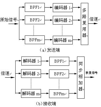
The picture above is a traditional way to divide the sub -band. In order to prevent the spectrum from confused, the filter is made, and then the extraction is performed. G ( Z ) G(Z) G(Z)and H ( Z ) H(Z) H(Z)They are called semi -bandwidth and low -pass and high -pass filters. In actual engineering, because the frequency division of the analysis filter is not perfect (there is still signal outside the deadline, there are leaks), mixed distortions will be introduced when pumping. This hybrid distortion has always existed in the subsequent processing and restore signals. The processing module in the neglect of the diagram can be used in the final signal.
s ^ ( z ) = 1 2 s ( z ) [ G 2 ( z ) − H 2 ( z ) ] + 1 2 s ( − z ) [ G ( z ) G ( − z ) − H ( z ) H ( − z ) ] \hat s(z)=\frac{1}{2}s(z)[G^2(z)-H^2(z)] + \frac{1}{2}s(-z)[G(z)G(-z)-H(z)H(-z)] s^(z)=21s(z)[G2(z)−H2(z)]+21s(−z)[G(z)G(−z)−H(z)H(−z)]
The left half of the upper equal number is the expected signal s ^ \hat s s^The filtering process can be regarded as a mixed distortion part after adding the number. Choose suitable G ( z ) G(z) G(z)and H ( z ) H(z) H(z)The part of the additional number is equal to zero, so that after passing the synthetic filter, it will have no impact on the result.
G ( z ) G(z) G(z)Harmony H ( z ) H(z) H(z)Formed an orthogonal mirror filter group, that is, H ( z ) = G ( − z ) H(z)=G(-z) H(z)=G(−z)At this time, the items after the increase can be met, and this orthogonal relationship can be achieved with a full -pass filter;
G ( z ) = 1 2 [ A 1 ( z 2 ) + z − 1 A 2 ( z 2 ) ] G(z)=\frac{1}{2}[A_1(z^2) + z^{-1}A_2(z^2)] G(z)=21[A1(z2)+z−1A2(z2)]
H ( z ) = 1 2 [ A 1 ( z 2 ) − z − 1 A 2 ( z 2 ) ] H(z)=\frac{1}{2}[A_1(z^2)-z^{-1}A_2(z^2)] H(z)=21[A1(z2)−z−1A2(z2)]
but

Then use the above full -pass filter to replace the orthopedic mirror image filter group to obtain the structure shown in the figure above. because A 1 ( z 2 ) A_1(z^2) A1(z2)and A 2 ( z 2 ) A_2(z^2) A2(z2)yes z z zThe puppet function can be placed before the filter, and the new structure can be obtained:

The above structure is a number of filter forms. When the molecular belt, first use a filter to add and reduce the results of the filter through one filter, and reduce the results of the two sub -bands of high -frequency and low -frequency bands.
The voice detection function Silk_vad_getsa_q8_c detecting the method of voice is similar to the principle of WebRTC detection, but the details are different. They are implemented by the method of dividing the molecular belt. Readers can refer to the author's "Real -time Voice Treatment Guide" related chapters. The division of the child is as follows:

Silk_ana_filt_bank_1 function is to implement the sampling of the sampling. The principle of the sampling below is as described as mentioned above, and the multi -phase filtering structure is achieved by two first -order full -pass filters to reduce the calculation amount. Array variable x_offset recorded 0 respectively 01kHz,12KHz, 2-4kHz, 4-8kHz four sub-bands of the domain point at the start and end offset position, and then calculate the energy of each child belt.
//VAD.c
82 opus_int silk_VAD_GetSA_Q8_c(
83     silk_encoder_state          *psEncC,                    // I/O encoder status
84     const opus_int16            pIn[]   )                   // I PCM input
86 {
129     // 0-8 KHz divided into 0-4 kHz and 4-8 kHz
130     silk_ana_filt_bank_1( pIn, &psSilk_VAD->AnaState[  0 ],
131         X, &X[ X_offset[ 3 ] ], psEncC->frame_length );
132
133     // 0-4 KHz is divided into 0-2 kHz and 2-4 kHz
134     silk_ana_filt_bank_1( X, &psSilk_VAD->AnaState1[ 0 ],
135         X, &X[ X_offset[ 2 ] ], decimated_framelength1 );
136
137     // 0-2 kHz is divided into 0-1 kHz and 1-2 kHz
138     silk_ana_filt_bank_1( X, &psSilk_VAD->AnaState2[ 0 ],
139         X, &X[ X_offset[ 1 ] ], decimated_framelength2 );
// Decimated_Framelength's length is 40. Here is the lowest frequency tape to use high -pass filtering,
// This is because people's voice is generally more than tens of Hertz, so the low -frequency signals are appropriately weakened.
146     for( i = decimated_framelength - 1; i > 0; i-- ) {
147         X[ i - 1 ]  = silk_RSHIFT( X[ i - 1 ], 1 );
148         X[ i ]     -= X[ i - 1 ];
149     }
153     /*************************************/
154     /* Calculate the energy of each sub -band*/
155     /*************************************/
156     for( b = 0; b < VAD_N_BANDS; b++ ) {
157         // Based on the position of the sub -band, calculate the number of domain points of the child belt. For the child belt 0, it is 40
158         decimated_framelength = silk_RSHIFT( psEncC->frame_length, silk_min_int( VAD_N_BANDS - b, VAD_N_BANDS - 1 ) );
159
160         // Calculate the number of time domains of the sub -band
161         dec_subframe_length = silk_RSHIFT( decimated_framelength, VAD_INTERNAL_SUBFRAMES_LOG2 );
162         dec_subframe_offset = 0;
163
164         // Traversing the energy of each sub -frame and calculating the energy of each sub -frame
165         // The energy of the energy of each child frame is the energy value of the previous subframes
166         Xnrg[ b ] = psSilk_VAD->XnrgSubfr[ b ];
167         for( s = 0; s < VAD_INTERNAL_SUBFRAMES; s++ ) {
168             sumSquared = 0;
169             for( i = 0; i < dec_subframe_length; i++ ) {
170                 // Energy value will be smaller than dec_subframe_length * (Silk_int16_min / 8) ^ 2. 2.
171                 // Unless DEC_SUBFRAME_LENGTH> 128), it will not occur if the sampling is directly accumulated here.
172                 x_tmp = silk_RSHIFT(
173                     X[ X_offset[ b ] + i + dec_subframe_offset ], 3 );
174                 sumSquared = silk_SMLABB( sumSquared, x_tmp, x_tmp );
178             }
179
180             // Calculate the energy of the current sub -frame
181             if( s < VAD_INTERNAL_SUBFRAMES - 1 ) {
182                 Xnrg[ b ] = silk_ADD_POS_SAT32( Xnrg[ b ], sumSquared );
183             } else {
184                 // The energy of the last sub -frame refers to the energy of the first subframe
185                 Xnrg[ b ] = silk_ADD_POS_SAT32( Xnrg[ b ], silk_RSHIFT( sumSquared, 1 ) );
186             }
187
188             dec_subframe_offset += dec_subframe_length;
189         }
190         psSilk_VAD->XnrgSubfr[ b ] = sumSquared;
191     }
Here are two for cycles. The first for loop traversing four sub -bands. The second for loop is traversing subframes. In OPUS, the internal PITCH analysis is based on 5MS frames. The parameters of the encoder in this book are 20ms. The universality of the program is achieved here with dual cycles. For examples of this book, 01kHz is the energy of the first 40 points (10 points, one sub -frame, four), similar 12KHz, 2-4KHz, 4-8kHz counted the energy of 40, 80, and 160 points respectively. In order to make the calculation convenient, the sub-frames in each child belt are continuously stored, and the sub-belt is also stored in order. Framelength2, decimated_framelength tagdoniability is implemented by the body.
4.1.7.2 VAD noise estimation
The VAD noise is estimated to be implemented by the Silk_vad_getNoiselevels function. The first parameter is the energy of each sub -band calculated in the previous section. The second parameter is the VAD state structure PSSILK_VAD.
//VAD.c
303 void silk_VAD_GetNoiseLevels(
304     const opus_int32            pX[ VAD_N_BANDS ],  // I sub -belt energy
305     silk_VAD_state              *psSilk_VAD         // I/O pointer to the Silk VAD state
306 )
307 {
     // 1000 = 20 SEC, the sliding value in the first 20 seconds is large, and it is used to accelerate noise convergence
313   if( psSilk_VAD->counter < 1000 ) {
         // pssilk_vad-> Counter is set to 15 when initialized, and its initial value affects the convergence time. MIN_COEF is the lower limit of the smooth noise
314      min_coef = silk_DIV32_16( silk_int16_MAX, silk_RSHIFT( psSilk_VAD->counter, 4 ) + 1 );
         // Frame meter numerical increasing
316      psSilk_VAD->counter++;
317   } else {
318      min_coef = 0;
319   }
   // for loop update noise level
321   for( k = 0; k < VAD_N_BANDS; k++ ) {
322      // Get the level of historical noise
323      nl = psSilk_VAD->NL[ k ];
326      // Add pink noise
327      nrg = silk_ADD_POS_SAT32( pX[ k ], psSilk_VAD->NoiseLevelBias[ k ] );
330      // Energy uses the maximum number of 32bit. The reason for this is that the energy is calculated based on the integer.
331      inv_nrg = silk_DIV32( silk_int32_MAX, nrg );
334      // Based on the current energy and historical energy, the update of the update of the noise is updated.
335      if( nrg > silk_LSHIFT( nl, 3 ) ) {
336         coef = VAD_NOISE_LEVEL_SMOOTH_COEF_Q16 >> 3;
337      } else if( nrg < nl ) {
338         coef = VAD_NOISE_LEVEL_SMOOTH_COEF_Q16;
339      } else {
340        coef = silk_SMULWB( silk_SMULWW( inv_nrg, nl ), VAD_NOISE_LEVEL_SMOOTH_COEF_Q16 << 1 );
341      }
343      // Get noise level update coefficient
344      coef = silk_max_int( coef, min_coef );
346      // Smooth noise INV_NRG is the current noise level, INV_NL is the historical noise level
347      psSilk_VAD->inv_NL[ k ] = silk_SMLAWB( psSilk_VAD->inv_NL[ k ], inv_nrg - psSilk_VAD->inv_NL[ k ], coef );
349
350      // After the calculation of the inverted domain is completed, the conversion back to the normal linear domain
351      nl = silk_DIV32( silk_int32_MAX, psSilk_VAD->inv_NL[ k ] );
353
354      // Limit the level of noise, ensure that 7 bits high are not used
355      nl = silk_min( nl, 0x00FFFFFF );
357      // Storage updated noise level
358      psSilk_VAD->NL[ k ] = nl;
359  }
The initialization of noise offset and noise estimation in the above code is as follows:
   // vad_n_bands is the macro of the definition domain define.h file, with a value of 4,
   // The initial offset value of the four sub -band noise is set to the pink noise in the natural environment. The power spectrum and frequency of pink noise are proportional.
   for( b = 0; b < VAD_N_BANDS; b++ ) {
        psSilk_VAD->NoiseLevelBias[ b ] = silk_max_32( silk_DIV32_16( VAD_NOISE_LEVELS_BIAS, b + 1 ), 1 );
    }

    // nl is the abbreviation of Noise Level. Inv_nl represents Inverse Noise Level
    // After setting here, the value of the nl sub -band is 50*100, 25*100, 16*100, 12*100
    for( b = 0; b < VAD_N_BANDS; b++ ) {
        psSilk_VAD->NL[ b ]     = silk_MUL( 100, psSilk_VAD->NoiseLevelBias[ b ] );
        psSilk_VAD->inv_NL[ b ] = silk_DIV32( silk_int32_MAX, psSilk_VAD->NL[ b ] );
    }
4.1.7.3 Calculation
Considering the fixed -point representation of energy, the sub -band calculation process has calculated the signal -to -noise ratio of the signal with noise signal
//VAD.c
203     for( b = 0; b < VAD_N_BANDS; b++ ) {
            // Use the energy of the current sub -frame to minimize the noise energy after smoothness and get voice energy
204         speech_nrg = Xnrg[ b ] - psSilk_VAD->NL[ b ];
205         if( speech_nrg > 0 ) {
206             // Calculate energy to signal -to -noise ratio. In order to ensure accuracy, the Q8 standard method is used
207             if( ( Xnrg[ b ] & 0xFF800000 ) == 0 ) {
208                 NrgToNoiseRatio_Q8[ b ] = silk_DIV32( silk_LSHIFT( Xnrg[ b ], 8 ), psSilk_VAD->NL[ b ] + 1 );
209             } else {
210                 NrgToNoiseRatio_Q8[ b ] = silk_DIV32( Xnrg[ b ], silk_RSHIFT( psSilk_VAD->NL[ b ], 8 ) + 1 );
211             }
213             // Here is the target method of LOG domain, which can compress the dynamic range of data, and has a good resolution in SNR for less hours
214             SNR_Q7 = silk_lin2log( NrgToNoiseRatio_Q8[ b ] ) - 8 * 128;
215
216             // The sum of the square with SNR
217             sumSquared = silk_SMLABB( sumSquared, SNR_Q7, SNR_Q7 );          /* Q14 */
218
219             /* Tilt measure */
220             if( speech_nrg < ( (opus_int32)1 << 20 ) ) {
221                 /* Scale down SNR value for small subband speech energies */
222                 SNR_Q7 = silk_SMULWB( silk_LSHIFT( silk_SQRT_APPROX( speech_nrg ), 6 ), SNR_Q7 );
223             }
   // ### Tilt Silk quotes Noise Shaping Analysis. Kasuya defines the difference between the peak power spectrum and the spectrum 2 ~ 3kHz power spectrum. "Spectral-Thilt Features of Emotional Speech-Research on Emotional Synthesis Based on Voice Quality Conventory
224             input_tilt = silk_SMLAWB( input_tilt, tiltWeights[ b ], SNR_Q7 );
225         } else {
                // In non -language conditions, the SNR is set to 0, and the Q8 is expressed as 256
226             NrgToNoiseRatio_Q8[ b ] = 256;
227         }
228     }
        // Sumsquared is the energy value of the four sub -bands, here is the average number of sub -bands.
231     sumSquared = silk_DIV32_16( sumSquared, VAD_N_BANDS ); /* Q14 */
        // Silk_sqrt_approx uses a balance of square root calculation. Here is a non -linear operation (the average square root and the calculation of numbers, and the Q14 becomes Q7 after the average root root.
234     pSNR_dB_Q7 = (opus_int16)( 3 * silk_SQRT_APPROX( sumSquared ) ); /* Q7 */
        // Voice probability estimates, realized through the SIGMOID function nonlinear mapping
239     SA_Q15 = silk_sigm_Q15( silk_SMULWB( VAD_SNR_FACTOR_Q16, pSNR_dB_Q7 ) - VAD_NEGATIVE_OFFSET_Q5 );
Silk_lin2log corresponds to 128 ∗ log 2 ( ) 128*\log_2() 128∗log2(), Q0 The SNR of SNR is available S N R = log ( N r g T o N o i s e R a t i o Q 8 [ b ] / 2 8 ) SNR=\log(NrgToNoiseRatio_{Q8}[ b ]/2^8) SNR=log(NrgToNoiseRatioQ8[b]/28)Calculate, by multiplied 2 7 = 128 2^7=128 27=128Obtain the way, Silk_lin2log (nRGTONOISERATIO_Q8 [B]) -8 * 128's approximation is:
128 ∗ log N r g T o N o i s e R a t i o Q 8 [ b ] − 8 ∗ 128 = 2 7 ∗ log 2 ( N r g T o N o i s e R a t i o Q 8 / 2 8 ) 128*\log{NrgToNoiseRatio_{Q8}[ b ] } - 8*128 = 2^7*\log_2{(NrgToNoiseRatio_{Q8}/2^8)} 128∗logNrgToNoiseRatioQ8[b]−8∗128=27∗log2(NrgToNoiseRatioQ8/28)
Q8 2 8 2^8 28To eliminate, 128 numbers are the displacement of the Q7 fixed standard (the multiplication method is implemented here).
y = 3 ⋅ x − log 2 x y=3 \cdot \sqrt{x} - \log_2 ^x y=3⋅x
−log2xThe image is as follows, PSNR_DB_Q7 By converting non -linear log calculation to a balanced calculation function Silk_SQRT_APPROX. Although the error exists, because SNR is a gate limit, the error is concentrated in the final position of the fixed standard, so the error effect is not great.
Convert SNR to voice probability through the SIGMOID function, the SIGMOID function y = 1 1 + e − x y=\frac{1}{1+e^{-x}} y=1+e−x1The image is as follows. It can restrict the value of x between (0 ~ 1), and the value is approximately approximately 1. This is in line with the non -linear relationship between voice probability and SNR. SIGMOID is also some activation functions based on deep learning models. It uses its non -linear interval mapping.

4.1.7.4 Spectrum tilt calculation
The SPECTRAL TILT is a weighted average from the sub -band SNR.
//Vad.c sub -band weight and weighing,
input_tilt = silk_SMLAWB( input_tilt, tiltWeights[ b ], SNR_Q7 );
// Similar to VAD calculation, it also transforms through the SIGMOID function
psEncC->input_tilt_Q15 = silk_LSHIFT( silk_sigm_Q15( input_tilt ) - 16384, 1 );
4.1.7.5 voice probability calculation
//Vad.c A shrinking of voice probability based on voice energy
249     speech_nrg = 0;
250     for( b = 0; b < VAD_N_BANDS; b++ ) {
// Because the high -frequency band has a small energy, it is weighted here (B+1) because it is 4 sub -belt, so the voice energy of each child belt divides 4 to obtain the average value of four characters
252         speech_nrg += ( b + 1 ) * silk_RSHIFT( Xnrg[ b ] - psSilk_VAD->NL[ b ], 4 );
253     }
// For the situation of 20ms frames, except 2 energy calculated by getting 10MS frames, here is a right -right operation.
255     if( psEncC->frame_length == 20 * psEncC->fs_kHz ) {
256         speech_nrg = silk_RSHIFT32( speech_nrg, 1 );
257     }
258     // According to the energy calculated earlier, adjust the probability of voice
259     if( speech_nrg <= 0 ) {// If it is less than zero, it means that it overflows when the energy calculation of the energy before. At this time, the value of SA_Q15 is reduced
260         SA_Q15 = silk_RSHIFT( SA_Q15, 1 );
261     } else if( speech_nrg < 16384 ) {
262         speech_nrg = silk_LSHIFT32( speech_nrg, 16 );
264         // Convert to Q15 for represented by the energy (32768 = 2^15)
265         speech_nrg = silk_SQRT_APPROX( speech_nrg );
266         SA_Q15 = silk_SMULWB( 32768 + speech_nrg, SA_Q15 );
267     }
269     // Report the final voice probability in the encoder status structure
270     psEncC->speech_activity_Q8 = silk_min_int( silk_RSHIFT( SA_Q15, 7 ), silk_uint8_MAX );
4.1.7.6 Voice quality estimation
//Vad.c Calculate the smooth factor of the voice/noise, the initial VAD_SNR_SMOOTH_COEF_Q18 corresponding to the floating point is 0.0156
276     smooth_coef_Q16 = silk_SMULWB( VAD_SNR_SMOOTH_COEF_Q18, silk_SMULWB( (opus_int32)SA_Q15, SA_Q15 ) );
277
278     if( psEncC->frame_length == 10 * psEncC->fs_kHz ) {
279         smooth_coef_Q16 >>= 1;
280     }
281
282     for( b = 0; b < VAD_N_BANDS; b++ ) {
283         // The smooth estimation of the voice/noise of each child belt
284         psSilk_VAD->NrgRatioSmth_Q8[ b ] = silk_SMLAWB( psSilk_VAD->NrgRatioSmth_Q8[ b ],
285             NrgToNoiseRatio_Q8[ b ] - psSilk_VAD->NrgRatioSmth_Q8[ b ], smooth_coef_Q16 );
286
287         // Calculate the pair domain SNR according to the signal -to -noise ratio
288         SNR_Q7 = 3 * ( silk_lin2log( psSilk_VAD->NrgRatioSmth_Q8[b] ) - 8 * 128 );
289         // According to the formula Quality = Sigmoid (0.25 * (SNR_DB -16));, calculate the voice quality
290         psEncC->input_quality_bands_Q15[ b ] = silk_sigm_Q15( silk_RSHIFT( SNR_Q7 - 16 * 128, 4 ) );
291     }
4.1.8 DTX settings
Because the OPUS and Silk modules have VAD detection, when the two have conflicts, the OPUS detection results are finalized. DTX is non -continuous transmission, which can greatly save bandwidth.
 44 void silk_encode_do_VAD_FLP(
 45     silk_encoder_state_FLP          *psEnc,                             // I/O encoder status
 46     opus_int                        activity                            // OPUS VAD detection
 47 )
 48 {
 49     const opus_int activity_threshold = SILK_FIX_CONST( SPEECH_ACTIVITY_DTX_THRES, 8 );
 50
 51     //4.1.7 Silk module VAD calculation
 54     silk_VAD_GetSA_Q8( &psEnc->sCmn, psEnc->sCmn.inputBuf + 1, psEnc->sCmn.arch );
 55     // If the final calculation result is that OpusVAD shows words without voice, and Silk VAD shows voice, which is based on OPUS. Set the VAD of SILK as the same as possible.
 56     if( activity == VAD_NO_ACTIVITY && psEnc->sCmn.speech_activity_Q8 >= activity_threshold ) {
 57         psEnc->sCmn.speech_activity_Q8 = activity_threshold - 1;
 58     }
Next, according to the statistics of VAD, calculate the status of DTX. If there is no voice in 200ms in a row, it will enter the DTX state. In the DTX mode, set the Psenc-> SCMN.VAD_FLAGS logo to zero, so that you can send the coding voice pack without sending it. The continuity of the non -language paragraph sounds.
Intelligent Recommendation

Linux system QT+Faac real-time audio acquisition coding (FAAC real-time coding)
The last time QT audio collection was published, this time is its follow-up content. Those who have not read the previous article can go to this link:Linux system QT+Faac real-time audio acquisition c...
Reprinted: iOS audio and video real-time acquisition hardware coding
Original address: My demo address:https://github.com/weiman152/LiveRecordDemo。 The swift version of the viewcontroller is the video capture part for reference. The OC part includes the acquisition and...
Android audio and video coding-> Microphone real -time collection PCM to AAC
Coding process Register all components av_register_all () Create a encapsulation format. Initize input and output context (open the output file) avio_open (), you can output to the local or network ad...
ffmpeg real -time collection coding audio and video data
ffmpeg real -time collection coding audio and video data Articles directory ffmpeg real -time collection coding audio and video data 1. Platform 2. Background environment 3. Data format definition 4. ...
Audio Codec - Opus
Introduction OpusIt is a completely open, royalty-free, versatile audio codec. It is suitable for interactive voice and music transmission over the Internet, but is also suitable for storage and strea...
More Recommendation
Transplantation OPUS Audio Decoding Library to FreeScale IMX6Q (Freedon Embedded OKMX6Q-C Development Board) platform
Transplantation OPUS Audio Decoding Library to FreeScale IMX6Q (Freedon Embedded OKMX6Q-C Development Board) platform Cross compiler The latest version of the cross-compilation tool chain provided by ...

Linux system QT+Faac real-time audio acquisition coding (QT audio acquisition articles)
I. Introduction Soon after graduation, the first project I received was audio collection. It is required to use QT to collect audio on the Raspberry Pi Linux system, and then encode and send it to a p...

STM32 audio coding and decoding on the PC side
STM32 audio coding and decoding on the PC side Introduction STM32F4 transplantation coding PC transplantation decoding end Introduction Those who can see this article are basically people who have urg...
OPUS introduction and compilation
OPUS is a format of lossy sound encoding, developed by IETF, no patent or restrictions, suitable for real-time sound transmission on the network, standard format is RFC 6716, its technology comes from...
Analysis of audio and video synchronization principles; audio coding and decoding principles
What exactly is DTS/PTS in the video stream? DTS (decoding time stamp) and PTS (display time stamp) are the time stamps relative to SCR (system reference) when the decoder decodes and displays frames,...