Implementation of vlanif configuration under eNSP simulation (one aggregation switch, two access switches) through the three-layer switch to realize the three-layer communication between VLANs
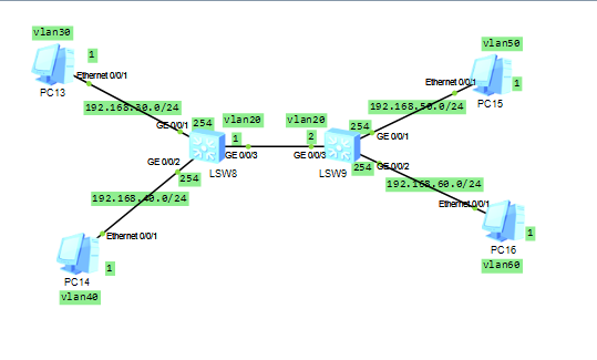
Experimental topology map:
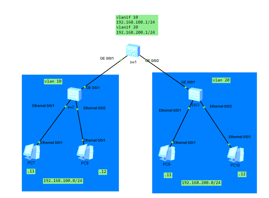
Problem analysis: Because this topology is a three-layer device. The access switches (sw2, sw3) are forwarding devices. You can regard vlan 10 as a PC as a whole, and similarly, vlan 20 is also a PC. So it can be simplified to a three-layer switch and two pc connections. Simplified can be regarded as a router and two pcs.
Experiment goal:
The network can communicate across different VLANs. That is, pc7ping to pc10. It can communicate under the same vlan. And under the same vlan. Can not go through the aggregation switch. But directly through the access switch.
Reason for implementation:
The reason why it can communicate across VLANs is that the aggregation switch can forward data packets to another VLAN.
Similarly, no configuration is required under vlan 10. Because access switch
Supplement:
The Layer 2 switch will not send arp packets to different network segments, and will only communicate within the same network segment.
A network host and B network host are not in the same network segment, assuming
A network address segment is: 192.168.10.0/24;
B network address segment is: 192.168.20.0/24;
A network host X (192.168.10.10/24) if you want to directly communicate with B network host Y (192.168.20.10/24),
X will not directly send an ARP request packet to request the MAC address of Y, but will request the MAC address of the gateway of the network segment (A network) where the X host is located. The network card will directly inform the system: "Destination host unreachable." and give up the communication.
So even if the ports of the switch are in the same broadcast domain, there is no need to worry about the communication between the A network and the B network.
In this topic, you only need to configure the ip address, gateway, and mask of sw1 and pc. The access switch does not require any configuration. The configuration of the pc is shown in the topology diagram.
<Huawei>sys
[Huawei]sysname sw1
[sw1]vlan batch 10 20
[sw1]interface  g0/0/1
[sw1-GigabitEthernet0/0/1]port link-type access //The interface type here is access instead of trunk//
[sw1-GigabitEthernet0/0/1]q
[sw1]interface g0/0/2
[sw1-GigabitEthernet0/0/2]port link-type access //The same is that the interface type is access//
[sw1-GigabitEthernet0/0/2]q
[sw1]vlan 10
[sw1-vlan10]port g0/0/1
[sw1-vlan10]q
[sw1]vlan 20
[sw1-vlan20]port g0/0/2
[sw1-vlan20]q

[sw1]int
[sw1]interface vlanif 10
[sw1-Vlanif10]ip address 192.168.100.1 24
[sw1-Vlanif10]q
[sw1]interface Vlanif 20
[sw1-Vlanif20]ip address 192.168.200.1 24
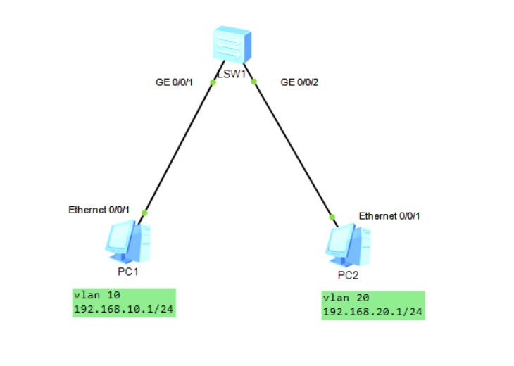
Is it possible to configure two PCs with different network segments under vlan 10. E.g
pc1:192.168.100.10/24
pc2:192.168.200.20/24
pc3:192.168.100.30/24
pc4:192.168.200.40/24
to realize the intercommunication between pc and pc
No
because when dividing vlan. The vlanif address at the port has been divided.
When pc2 accesses pc3, pc2 cannot forward packets through the aggregation switch. The gateway cannot be found at all.
is the vlan 10 currently allocated at g0/0/1
followed by vlanif. vlanif is not the ip address allocated at the interface. But the ip allocated on the vlan.
That means the gateway in vlan 10 is 192.168.100.1. Only the IP in this network segment can be forwarded.
and
Through the analysis of the packet capture at e0/0/2
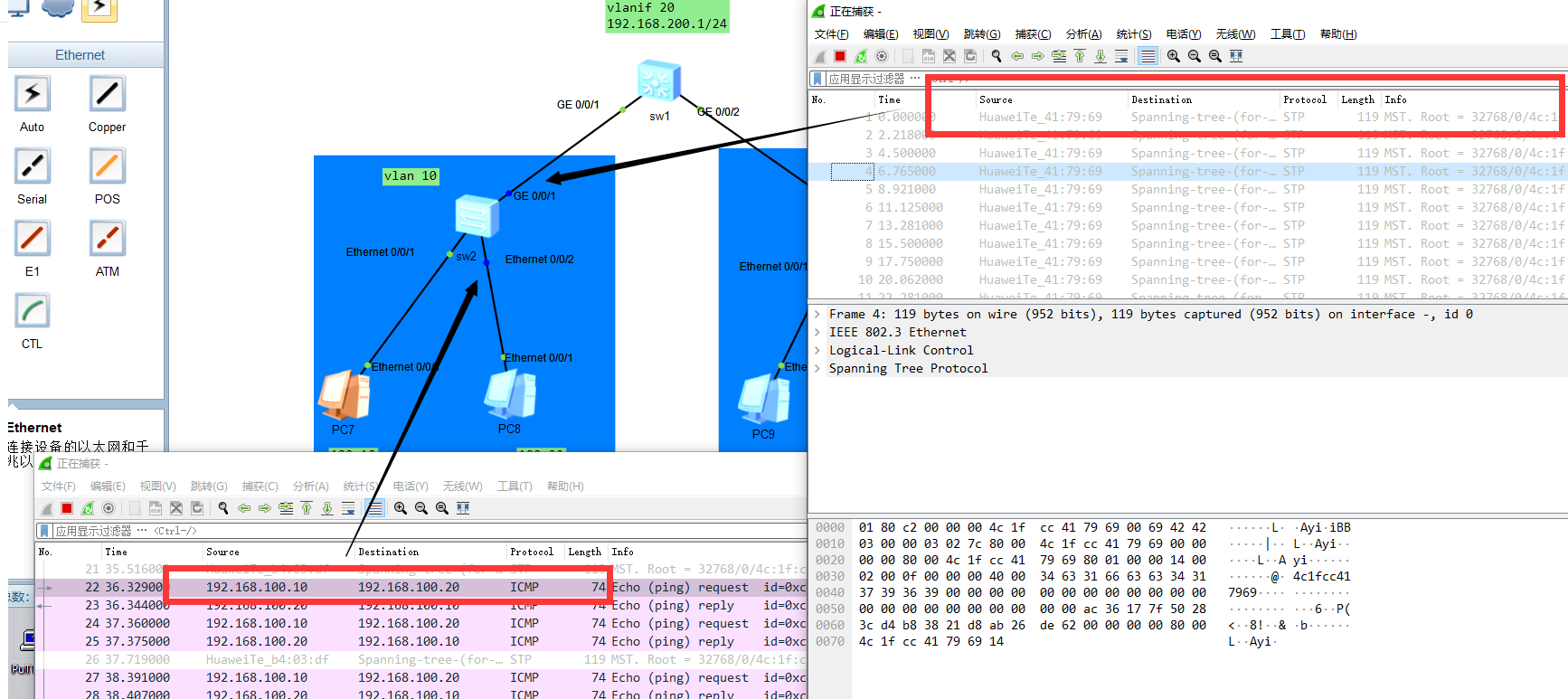
Ping packets under the same vlan
will not go through the aggregation switch sw1
Intelligent Recommendation

Experiment 2: Communication between VLANs with a three-layer switch
Experiment 2: Communication between VLANs with a three-layer switch First, experimental purpose and requirements OBJECTIVE: To master the VLAN configuration method of the various ports of the switch; ...
Huawei's three-layer switch realizes communication between different vlans
First, we need a layer 3 switch and two PCs We first create different vlan10 and vlan20 on the switch, and then assign the corresponding vlan to each port of the switch. Then configure the correspondi...

Use Huawei's three-layer switch to achieve mutual access between VLANs
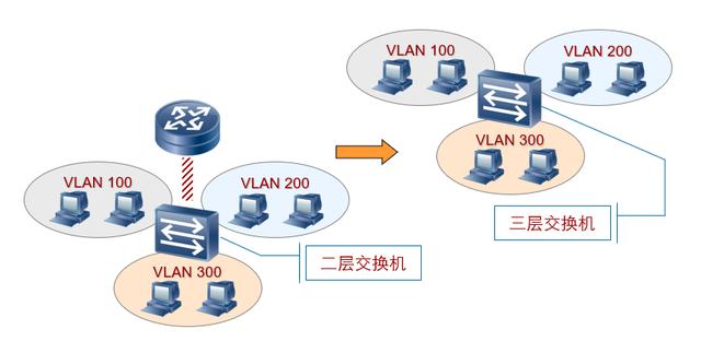
With the gradual increase of enterprise internal traffic, using the one-arm routing function of routers to achieve mutual access between different VLANs can no longer meet the needs of enterprise user...
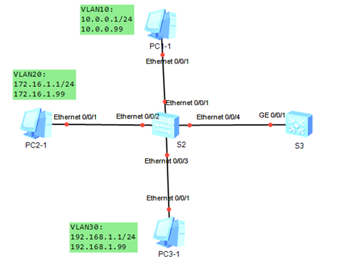
Huawei ENSP VLANIF implementation three-layer communication experiment
Experiment Topology: Experimental description: 1. Modify the switch name to S2 S3 2. Be properly configured on S2 S3 so that the three VLANs can communicate Experimental configuration: Test connectivi...
Using single-arm routing and three-layer switch to realize data communication between different VLANs
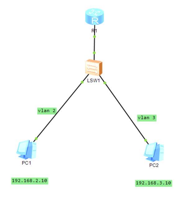
@cenjealTwo ways of data communication between different VLANs 1. Use layer 2 switch + router (single arm routing) 1.1 PC1 configuration Manually configure the IP address of pc1: 192.168.2.10 Subnet m...
More Recommendation
5 -> Routing between VLANs (three-layer switch)
This reprint is4-> VLAN principle detailed Continue, considering the article space, dividing the second part. 1. VLAN route 1.1 Necessity of VLAN Route According to the knowledge learned so far, we...
ensp exercise: Layer 3 switch realizes communication between VLANs
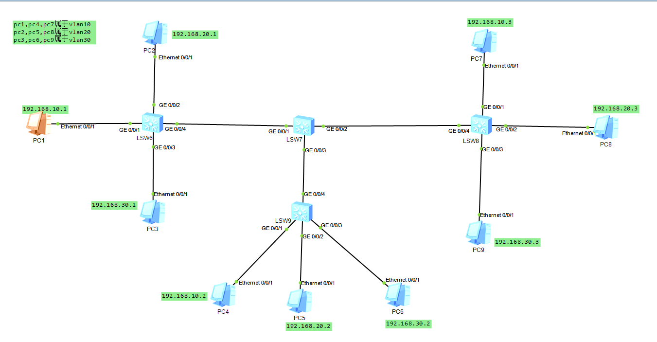
Because different VLANs cannot communicate, experiment with the communication between different VLANs through the configuration of the switch 1: Experimental topology put here pc1, pc4, pc7 all belong...
Communication between different VLANs between the three-layer switches
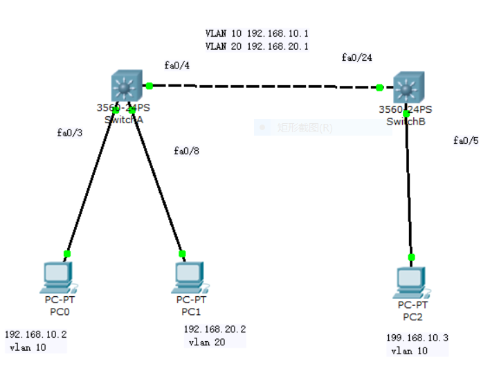
Purpose: Verify that different hosts in VLAN can communicate Topology: Experimental steps: 1. Configure a three-layer switch Switcha 2, configure three-layer switch Switchb 3, set the IP and subnet ma...
Huawei ENSP three -layer switch configuration uses VLAN and OSPF communication
The experiment topology is as follows: Configure the host IP address and port IP address in advance Remark:The interface of PC, router, and server generally uses Access The configuration of the...
Introduction to the Three -layer Switch Principle of Communication Three -layer Switch between Third Layer Interface and Two Layer interfaces
Vlanif logic interface to implement Configure the VLANIF interface on the three -layer switch to implement the VLAN interstitial route What is a three -layer switch The functional integration of the t...