SPI、I2C、UART、CAN
tags: SPI communication I2C communication UART communication CAN communication SPI、I2C、UART、CAN
First, the introduction
1. SPI
SPI (Serial Peripheral Interface) is a synchronous serial data transmission standard proposed by Motorola, which is widely used in many devices.
- interface
The SPI interface is often referred to as a 4-wire serial bus and operates in master/slave mode. The data transfer process is initiated by the host. As shown in Figure 1, the four signal lines used are:
1) SCLK: serial clock, used to synchronize data transmission, output by the host;
2) MOSI: The host outputs the slave input data line, usually transmitting the MSB first;
3) MISO: The host inputs the slave output data line, usually transmitting the LSB first;
4) SS: Chip select line, active low, output by the host.
On the SPI bus, multiple slaves can appear at a time, but only one master can exist. The master determines the slave to communicate through the chip select line. This requires the slave's MISO port to have a tri-state characteristic such that the port line exhibits high impedance when the device is not gated.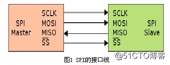
- data transmission
In one SPI clock cycle, the following operations are completed:
1) The host sends 1-bit data through the MOSI line, and the slave reads the 1-bit data through the line;
2) The slave transmits 1-bit data through the MISO line, and the host reads the 1-bit data through the line.
This is done through the shift register. As shown in Figure 2, the master and slave each have a shift register, and the two are connected in a loop. With the clock pulse, the data is sequentially shifted out of the master and slave registers in order from high to low, and sequentially into the slave and master registers. When all the contents of the register are removed, it is equivalent to completing the exchange of the contents of the two registers.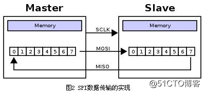
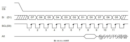
- Clock polarity and clock phase
The two most important settings in SPI operation are clock polarity (CPOL or UCCKPL) and clock phase (CPHA or UCCKPH). The clock polarity sets the level at which the clock is idle, and the clock phase sets the clock edge for reading data and transmitting data.
The data sent by the master and the slave are completed at the same time, and the received data of both is completed at the same time. Therefore, in order to ensure the correct communication between the master and the slave, their SPI should have the same clock polarity and clock phase.
For example, the MSP430 controller and the OLED driver SH1101A are selected as master and slave, respectively, and Figures 3 and 4 show their SPI timing. As can be seen from Figure 4, when the SH1101A's SPI clock is idle and is high, and the data is received on the trailing clock edge, the MSP430 controller SPI settings should be consistent with this. As can be seen from Figure 3, to make the clock high when idle, UCCKPL should be set to 1; to enable data to be received on the trailing clock edge, UCCKPH should be cleared.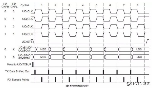
- Advantages and disadvantages
The SPI interface has the following advantages:
1) Support full-duplex operation;
2) Simple operation;
3) The data transfer rate is high.
At the same time, it also has the following disadvantages:
1) Need to occupy more lines of the host (each slave needs a chip selection line);
2) Only a single host is supported.
2. I2C
- interface
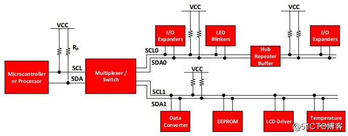
The I2C interface includes a clock line (SCL) and a data line (SDA). Both of these lines are open-drain or open-collector structures. When used, a pull-up resistor is required to mount multiple devices. Each device has its own address, and the host selects different devices through different addresses. - General operation
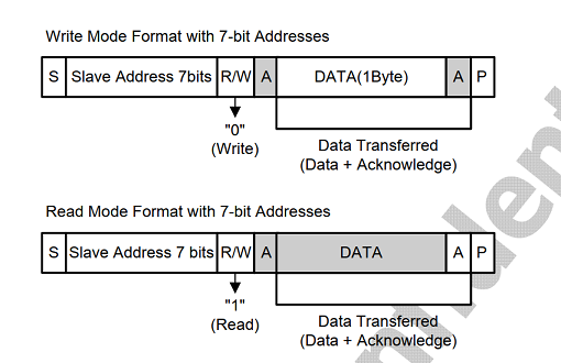
1) The host sends data to the slave- Send start condition START and slave address;
- send data;
- The transmission stop condition STOP ends.
2) The host reads data from the slave - Send start condition START and slave address;
- Send the address to be read;
- Read data;
- The transmission stop condition STOP ends.
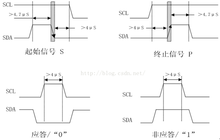
2.1 start and end conditions
When SCL is held high, SDA transitions from high to low, which is the START condition. While SCL is held high, SDA transitions from low to high, which is the end condition STOP.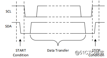
2.2 Repeated start conditions
The difference between and the start condition is that it appears before the end condition STOP. For example, when reading data, after sending START, slave address, and address to be read, there is no need to send STOP, but you can send a repeat start condition and a slave address to start data reading.
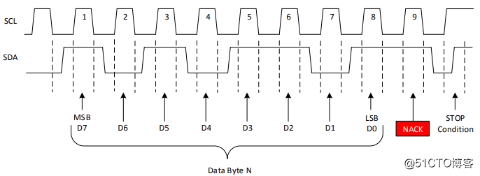
2.3 ACK and NACK
The MSB is transmitted first during data transmission. The receiver keeps SDA low for the ninth clock cycle after each byte to confirm that the data reception is successful; while holding the SDA high for the ninth clock cycle, the data transmission error occurs, or the host no longer wants to receive data.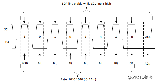
- Data reading and writing
1) Write data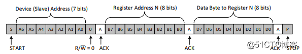
2) Read data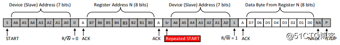
- Advantages and disadvantages
1) Advantages
uses only two signal lines;
supports multi-master multi-slave;
has a response mechanism.
2) Disadvantages
The rate is slower than SPI.
- Data reading and writing
3. UART
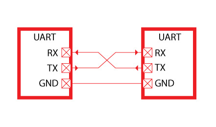
The UART is an asynchronous transfer interface that does not require a clock line and is identified by the start and stop bits and the baud rate.
- interface
The UART uses only two lines TXD and RXD for data transmission and reception.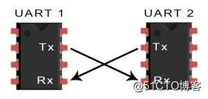
- Data Format
1) Start bit
The data line idle state is high, and it is pulled low for one clock cycle to indicate the start bit.
2) Data bits
When using the check digit, the data bits can have 5~8 bits; if the check digit is not used, the data bits can reach 9 bits.
3) Check digit
Parity, ensuring that the number of 1s in all bits including the check digit and the data bit is odd or even.
4) Stop bit
In order to indicate the end of the packet, the sender needs to change the signal line from low to high for at least 2 clock cycles. - Advantages and disadvantages
1) Advantages
uses only two signal lines;
does not require a clock signal;
has a check digit for error detection;
2) Disadvantages
The transfer rate is low.
4. CAN
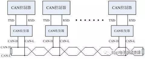
CAN, known as the "Controller Area Network", is the controller area network, and is one of the most widely used fieldbuses in the world. Initially, CAN was designed as a microcontroller communication in an automotive environment, exchanging information between the vehicle's electronic control unit ECUs to form an automotive electronic control network. For example, the engine management system, the gearbox controller, the instrumentation equipment, and the electronic trunk system are all embedded in the CAN control device.
In a single network consisting of a CAN bus, theoretically many nodes can be attached. In practical applications, the number of nodes is limited by the electrical characteristics of the network hardware. For example, when using the Philips P82C250 as a CAN transceiver, 110 nodes are allowed to be attached to the same network. CAN provides data transfer rates of up to 1 Mbit/s, making real-time control very easy. In addition, the hardware's error detection feature also enhances the CAN's immunity to electromagnetic interference.
CAN bus features:
1) It can work in multi-master mode. Any node on the network can actively send information to other nodes on the network at any time, regardless of master-slave, and the communication mode is flexible.
2) Nodes on the network can be divided into different priorities to meet different real-time requirements.
3) Using a non-destructive bit arbitration bus structure mechanism, when two nodes simultaneously transmit information to the network, the node with the lower priority actively stops the data transmission, and the node with the higher priority can continue to transmit the data without being affected.
4) It can be point-to-point, point-to-multipoint and global broadcast to receive data in several transmission modes.
5) The direct communication distance can be up to 10km (rate below 4Kbps).
6) The communication rate can be up to 1MB/s (the distance is up to 40m).
Second, the contrast
Both SPI and I2C communication methods are short-distance, communication between chips and chips or between other components such as sensors and chips. SPI and IIC are on-board communication, IIC sometimes also communicates between boards, but the distance is very short, but more than one meter, such as some touch screens, mobile phone LCD screens, many of the film cables use IIC, I2C can be used to replace the standard parallel Bus, various integrated circuits and functional modules that can be connected. I2C is a multi-master bus, so any device can work like a master and control the bus. Each device on the bus has a unique address that can operate as a transmitter or receiver depending on their capabilities. Multiplex microcontrollers can coexist on the same I2C bus. These two lines are low speed transmissions.
The UART is used for communication between two devices, such as the communication between the device and the computer. Such communication can be done over long distances. UART speed is faster than the above two, up to about 100K, with computer and equipment or computer and computing communication, but the effective range will not be very long, about 10 meters, UART advantage is wide support, programming structure Quite simply, with the development of USB, the UART is gradually going downhill.
The CAN communication distance is up to 10 km (set at 5 Kbps), or the maximum communication rate is 1 Mbps (set communication distance is 40 m).
The number of nodes on the CAN bus can reach 110. The communication medium can be selected from twisted pair, coaxial cable, and fiber.
CAN uses non-destructive bus arbitration technology. When multiple nodes send data at the same time, the node with lower priority will actively exit the transmission, and the node with high priority can continue to send, saving the bus. Arbitration time.
CAN works in a multi-master mode, and any node on the network can actively send information to other nodes on the network at any time.
CAN uses the message identifier to identify nodes on the network, so that the nodes are divided into different priorities, and the nodes with high priority enjoy the priority of transmitting messages. The message is a short frame structure, the short transmission time makes it less susceptible to interference, and CAN has a good validation mechanism, which ensures the reliability of CAN communication.
reference:
Intelligent Recommendation

UART, I2C, SPI communication protocol
UART UART: Universal Asynchronous Receiver/Transmitter, is a kind of asynchronous receiver/transmitter. It converts the data to be transmitted between serial communication and parallel communication. ...
UART/SPI/I2C comparative study
As shown below Some features should be added UART has a long transmission distance because there is no clock line, up to 15m, but the speed is very slow SPI supports full-duplex communication, simple ...

Communication protocol UART, I2C and SPI
1. What is a communication protocol To put it in the vernacular, the communication protocol is the rule agreed upon by both parties during communication. To make an analogy, just like you communicate ...
The difference between SPI, I2C, and UART
SPI: High-speed synchronous serial port. 3 ~ 4 line interface, send and receive independence, can be synchronously UART: Universal asynchronous serial port. Complete two-way communication according to...
Serial communication SPI, UART, I2C
Serial communication Articles directory Serial communication 1.SPI 1. Introduction to the four data cables: 2. Data transmission: 3. Clock polarity and clock phase 4. Advantages and disadvantages: 5. ...
More Recommendation

Serial communication UART, I2C, SPI
Serial communication UART, I2C, SPI Article Directory Serial communication UART, I2C, SPI 1.SPI 1. Introduction of four data lines: 2. Data transmission: 3. Clock polarity and clock phase 4. Advantage...
Common communication protocols I2C, SPI, UART .....
A correlation term: 1.1 serial: In a computer bus or other data channel, each transmission a byte of data, and continuously over a single communication process 1.2 Parallel: multi-bit data is simultan...

[Knowledge sharing] SPI, I2C and UART bus
When we are in DIY electronic products, in addition to the function of each module and equipment, we also need to consider the communication between them. The modules in electronic products are just l...
USB/UART/I2C/SPI interface transfer rate
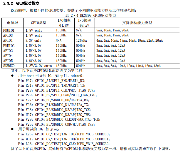
table of Contents USB bus UART I2C bus SPI bus GPIO(RK3399) FMC reference USB bus USB1.1: ——-low speed mode (low speed): 1.5Mbps ——-full speed mode (full speed): 12Mbps USB2.0:...
I2C, UART, SPI detailed explanation and differences
1. Communication 1. The concept of communication We call the information exchange between the computer and the outside world communication. 2. Classification of communication methods There are two bas...