Cisco builds a small local area network (Layer 3 switches and routers, ospf dynamic routing configuration)
tags: Build the network local area network router switch Network protocol
1. Training content:
- Architecture analysis
(1) Demand analysis
The purpose of this experiment is to establish a small local area network. Since the company is composed of different departments and distributed in different locations, different networks need to be divided to achieve interconnection. Design the following network: the two departments are connected by a switch, and then connected to the main switch, and then connected to the external network and other department networks through the router. In order to control the broadcast storm on the network and increase the security of the network, VLANs need to be set on the switch, and dynamic routing OSPF protocol needs to be set between the router and the switch.
(2) Environmental requirements
Cisco simulator - Planning the topology
(1) Topological description
Location 1 includes Department 1 and Department 2; Location 2 includes Department 3.
The department 1 network is subnet 3: 172.16.3.0/24, which corresponds to VLAN 3.
The department 2 network is subnet 9: 172.16.9.0/24, corresponding to VLAN9.
The computers of department 1 and department 2 are connected through switches S1 and S2 respectively, and then interconnected through the main switch S3.
S3 is connected to router R1, and R1 is connected to the department 3 network subnet 5:10.0.5.0/24 of site 2 through R2.
(2) Topological diagram
Note: The router uses AR2220.
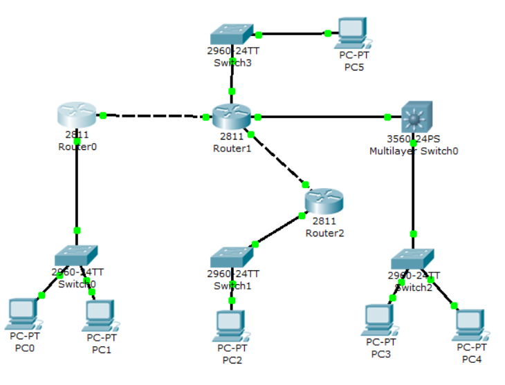
The topology of this small LAN is shown in Figure 2-3-1.
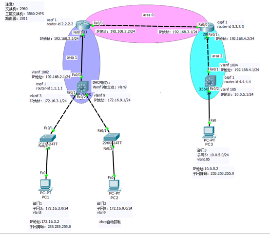
Figure 2-3-1 Small LAN topology
2. Description of configuration process
(1) Switch
S1: You need to create a vlan, configure access and trunk interfaces, and add the corresponding interface to the corresponding vlan3.
S2: You need to create a vlan, configure access and trunk interfaces, and add the corresponding interface to the corresponding vlan9.
S3: You need to create vlan, configure access and trunk interfaces, configure vlanif 3 and vlanif 9 interfaces and their IP addresses, create vlan1002, and configure vlanif 1002 interfaces and their IP addresses 192.168.2.1/24.
S4: You need to create vlan, configure access and trunk interfaces, configure vlanif 105 interface and its IP address, create vlan1004, and configure vlanif 1004 interface and its IP address 192.168.4.1/24.
(2) Router
R1: Configure the IP address of each interface and configure the OSPF protocol.
R2: Configure the IP address of each interface and configure the OSPF protocol.
3. Equipment configuration
(1) S1 configuration steps
Switch>en
Switch#conf t
Switch(config)#hostname S1
S1(config)#vlan 3
S1(config-vlan)#vlan 9
S1(config-vlan)#vlan 1002
S1(config-vlan)#exit
S1(config)#int f0/3
S1(config-if)#switchport access vlan 3
S1(config-if)#int f0/1
S1(config-if)#switchport mode trunk
S1(config-if)#
(2) S2 configuration steps
Switch>en
Switch#conf t
Switch(config)#hostname S2
S2(config)#vlan 3
S2(config-vlan)#vlan 9
S2(config-vlan)#vlan 1002
S2(config-vlan)#exit
S2(config)#int f0/3
S2(config-if)#switchport access vlan 9
S2(config-if)#int f0/1
S2(config-if)#switchport mode trunk
S2(config-if)#
(3) S3 configuration steps
Switch>en
Switch#conf t
Switch(config)#hostname S3
S3(config)#ip routing
S3(config)#vlan 3
S3(config-vlan)#vlan 9
S3(config-vlan)#vlan 1002
S3(config-vlan)#exit
S3(config)#int f0/1
S3(config-if)#switchport mode trunk
Command rejected: An interface whose trunk encapsulation is “Auto” can not be configured to “trunk” mode.
S3(config-if)#int f0/2
S3(config-if)#switchport mode trunk
Command rejected: An interface whose trunk encapsulation is “Auto” can not be configured to “trunk” mode.
S3(config-if)#int f0/3
S3(config-if)#switchport access vlan 1002
S3(config-if)#no shutdown
S3(config-if)#exit
S3(config)#
S3(config)#int vlan 3
S3(config-if)#ip address 172.16.3.1 255.255.255.0
S3(config-if)#int vlan 9
S3(config-if)#ip address 172.16.9.1 255.255.255.0
S3(config-if)#int vlan 1002
S3(config-if)#ip address 192.168.2.1 255.255.255.0
S3(config)#router ospf 1
S3(config-router)#router-id 1.1.1.1
S3(config-router)#network 172.16.3.0 0.0.0.255 area 1
S3(config-router)#network 172.16.9.0 0.0.0.255 area 1
S3(config-router)#network 192.168.2.0 0.0.0.255 area 1
S3(config)#service dhcp
S3(config)#ip dhcp pool vlan9
S3(dhcp-config)#network 172.16.9.0 255.255.255.0
S3(dhcp-config)#default-router 172.16.9.1
S3(dhcp-config)#dns-server 8.8.8.8
(4) S4 configuration steps
Switch>en
Switch#conf t
Switch(config)#hostname S4
S4(config)#ip routing
S4(config)#vlan 105
S4(config-vlan)#vlan 1004
S4(config-vlan)#exit
S4(config)#int f0/1
S4(config-if)#switchport access vlan 1004
S4(config-if)#no shutdown
S4(config-if)#int f0/2
S4(config-if)#switchport access vlan 105
S4(config-if)#exit
S4(config)#int vlan 105
S4(config-if)#ip address 10.0.5.1 255.255.255.0
S4(config-if)#int vlan 1004
S4(config-if)#ip address 192.168.4.1 255.255.255.0
S4(config-if)#exit
S4(config)#router ospf 1
S4(config-router)#router-id 4.4.4.4
S4(config-router)#network 192.168.4.0 0.0.0.255 area 2
S4(config-router)#network 10.0.5.0 0.0.0.255 area 2
(5) R1 configuration steps
Router>en
Router#conf t
Router(config)#hostname R1
R1(config)#int f0/1
R1(config-if)#ip address 192.168.2.2 255.255.255.0
R1(config-if)#no shutdown
R1(config-if)#int f0/0
R1(config-if)#ip address 192.168.3.2 255.255.255.0
R1(config-if)#no shutdown
R1(config-if)#exit
R1(config)#router ospf 1
R1(config-router)#router-id 2.2.2.2
R1(config-router)#network 192.168.2.0 0.0.0.255 area 1
R1(config-router)#network 192.168.3.0 0.0.0.255 area 0
(6) R2 configuration steps
Router>en
Router#conf t
Router(config)#hostname R2
R2(config)#int f0/0
R2(config-if)#ip address 192.168.3.1 255.255.255.0
R2(config-if)#no shutdown
R2(config-if)#int f0/1
R2(config-if)#ip address 192.168.4.2 255.255.255.0
R2(config-if)#no shutdown
R2(config-if)#exit
R2(config)#router ospf 1
R2(config-router)#router-id 3.3.3.3
R2(config-router)#network 192.168.3.0 0.0.0.255 area 0
R2(config-router)#network 192.168.4.0 0.0.0.255 area 2
- View routing table
(1) View S3 switch routing table
S3#show ip route
Codes: C - connected, S - static, I - IGRP, R - RIP, M - mobile, B - BGP
D - EIGRP, EX - EIGRP external, O - OSPF, IA - OSPF inter area
N1 - OSPF NSSA external type 1, N2 - OSPF NSSA external type 2
E1 - OSPF external type 1, E2 - OSPF external type 2, E - EGP
i - IS-IS, L1 - IS-IS level-1, L2 - IS-IS level-2, ia - IS-IS inter area
-
- candidate default, U - per-user static route, o - ODR
P - periodic downloaded static route
- candidate default, U - per-user static route, o - ODR
Gateway of last resort is not set
10.0.0.0/24 is subnetted, 1 subnets
O IA 10.0.5.0 [110/4] via 192.168.2.2, 00:12:44, Vlan1002
172.16.0.0/24 is subnetted, 2 subnets
C 172.16.3.0 is directly connected, Vlan3
C 172.16.9.0 is directly connected, Vlan9
C 192.168.2.0/24 is directly connected, Vlan1002
O IA 192.168.3.0/24 [110/2] via 192.168.2.2, 00:12:54, Vlan1002
O IA 192.168.4.0/24 [110/3] via 192.168.2.2, 00:12:44, Vlan1002
S3#
(2) View R1 router routing table
R1#show ip route
Codes: C - connected, S - static, I - IGRP, R - RIP, M - mobile, B - BGP
D - EIGRP, EX - EIGRP external, O - OSPF, IA - OSPF inter area
N1 - OSPF NSSA external type 1, N2 - OSPF NSSA external type 2
E1 - OSPF external type 1, E2 - OSPF external type 2, E - EGP
i - IS-IS, L1 - IS-IS level-1, L2 - IS-IS level-2, ia - IS-IS inter area
-
- candidate default, U - per-user static route, o - ODR
P - periodic downloaded static route
- candidate default, U - per-user static route, o - ODR
Gateway of last resort is not set
10.0.0.0/24 is subnetted, 1 subnets
O IA 10.0.5.0 [110/3] via 192.168.3.1, 00:14:00, FastEthernet0/0
172.16.0.0/24 is subnetted, 2 subnets
O 172.16.3.0 [110/2] via 192.168.2.1, 00:02:24, FastEthernet0/1
O 172.16.9.0 [110/2] via 192.168.2.1, 00:02:14, FastEthernet0/1
C 192.168.2.0/24 is directly connected, FastEthernet0/1
C 192.168.3.0/24 is directly connected, FastEthernet0/0
O IA 192.168.4.0/24 [110/2] via 192.168.3.1, 00:14:00, FastEthernet0/0
R1#
(3) View R2 router routing table
R2#show ip route
Codes: C - connected, S - static, I - IGRP, R - RIP, M - mobile, B - BGP
D - EIGRP, EX - EIGRP external, O - OSPF, IA - OSPF inter area
N1 - OSPF NSSA external type 1, N2 - OSPF NSSA external type 2
E1 - OSPF external type 1, E2 - OSPF external type 2, E - EGP
i - IS-IS, L1 - IS-IS level-1, L2 - IS-IS level-2, ia - IS-IS inter area
-
- candidate default, U - per-user static route, o - ODR
P - periodic downloaded static route
- candidate default, U - per-user static route, o - ODR
Gateway of last resort is not set
10.0.0.0/24 is subnetted, 1 subnets
O 10.0.5.0 [110/2] via 192.168.4.1, 00:18:58, FastEthernet0/1
172.16.0.0/24 is subnetted, 2 subnets
O IA 172.16.3.0 [110/3] via 192.168.3.2, 00:03:19, FastEthernet0/0
O IA 172.16.9.0 [110/3] via 192.168.3.2, 00:03:09, FastEthernet0/0
O IA 192.168.2.0/24 [110/2] via 192.168.3.2, 00:15:03, FastEthernet0/0
C 192.168.3.0/24 is directly connected, FastEthernet0/0
C 192.168.4.0/24 is directly connected, FastEthernet0/1
R2#
(4) View S4 switch routing table
S4#show ip route
Codes: C - connected, S - static, I - IGRP, R - RIP, M - mobile, B - BGP
D - EIGRP, EX - EIGRP external, O - OSPF, IA - OSPF inter area
N1 - OSPF NSSA external type 1, N2 - OSPF NSSA external type 2
E1 - OSPF external type 1, E2 - OSPF external type 2, E - EGP
i - IS-IS, L1 - IS-IS level-1, L2 - IS-IS level-2, ia - IS-IS inter area
-
- candidate default, U - per-user static route, o - ODR
P - periodic downloaded static route
- candidate default, U - per-user static route, o - ODR
Gateway of last resort is not set
10.0.0.0/24 is subnetted, 1 subnets
C 10.0.5.0 is directly connected, Vlan105
172.16.0.0/24 is subnetted, 2 subnets
O IA 172.16.3.0 [110/4] via 192.168.4.2, 00:04:10, Vlan1004
O IA 172.16.9.0 [110/4] via 192.168.4.2, 00:04:00, Vlan1004
O IA 192.168.2.0/24 [110/3] via 192.168.4.2, 00:15:54, Vlan1004
O IA 192.168.3.0/24 [110/2] via 192.168.4.2, 00:16:55, Vlan1004
C 192.168.4.0/24 is directly connected, Vlan1004
S4#
4 Configure the PC address
(1) Configure PC1 address
IP address: 172.16.3.2
Subnet mask: 255.255.255.0
Gateway: 172.16.3.1
(2) Configure PC2 address
Set to DHCP to obtain IP address dynamically
(3) Configure PC3 address
IP address: 10.0.5.2.
Subnet mask: 255.255.255.0
Gateway: 10.0.51
5. Network connectivity test
(1) PC1 connectivity test
PC1 (172.16.3.2) ping PC2 (172.16.9.2), you can ping through
PC1 (172.16.3.2) ping PC3 (10.0.5.2), you can ping through
PC2 (172.16.9.2) ping PC1 (172.16.3.2), you can ping through
PC2 (172.16.9.2) ping PC3 (10.0.5.2), you can ping through
PC3 (10.0.5.2) ping PC1 (172.16.3.2), you can ping through
PC3 (10.0.5.2) ping PC2 (172.16.9.2), you can ping through
Intelligent Recommendation
Cisco-OSPF dynamic routing
PC0 belongs to 100.100.100.0/24 PC1 belongs to 110.110.110.0/24 PC2 belongs to 120.120.120.0/24 PC3 belongs to 130.130.130.0/24 PC4 belongs to 140.140.140.0/24 PC5 belongs to 150.150.150.0/24 Configur...
Cisco Layer 3 switches implement inter-vlan routing explanation and configuration commands, the configuration process is very detailed
Cisco Layer 3 switches realize the configuration of routing between VLANs 1. The configuration topology diagram of Cisco Layer 3 switches to realize routing between VLANs 2. The detailed configuration...

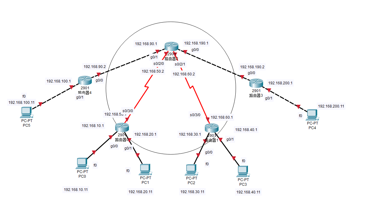
Cisco Simulator CIsco Packet Tracer Router OSPF Dynamic Routing Configuration
Copyright statement: If you are helpful to everyone, you can reprint it yourself. 1. Technical principle OSPF Open Shortest Path First Protocol is one of the most widely used routing protocols in the ...
OSPF dynamic routing configuration in Cisco Packet Tracer Cisco Simulation
OSPF (Open SHORTST PATH FIRST, the shortest open path) protocol is one of the most widely used dynamic routing protocols in the network. It also belongs to the internal gateway route protocol. It can ...
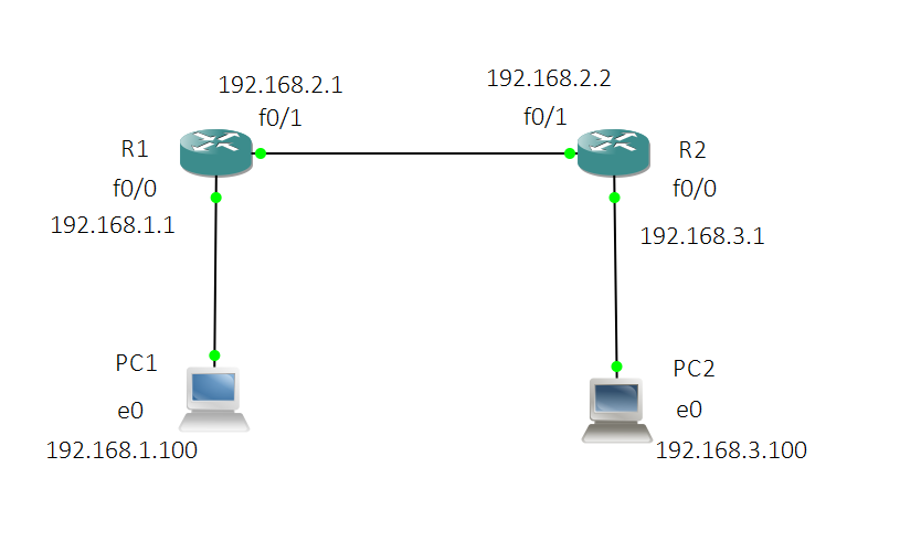
Static routing configuration in Cisco routers
In daily life, when we communicate with each other, we are not on the same network segment. Mainly rely on the function of forwarding data by router. This time, we will configure static routes on the ...
More Recommendation
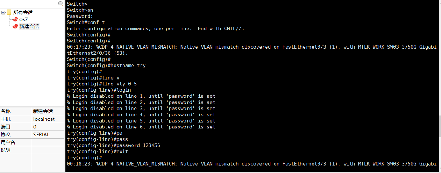
Remote login configuration of Cisco routers and switches
router #Enter privileged mode (privileged mode-view user level, exit, switch test, etc.) Router>en (or enable) #Exit Router#exit (or end) #Enter global mode Router#configure terminal #Enter port 0/...

Static routing and OSPF route redistribution with Layer 3 switches
Layer 3 switches are widely used in local area networks due to their fast forwarding speed. Next, combine the Layer 3 switch and the router to configure static routing and OSPF route redistribution. B...
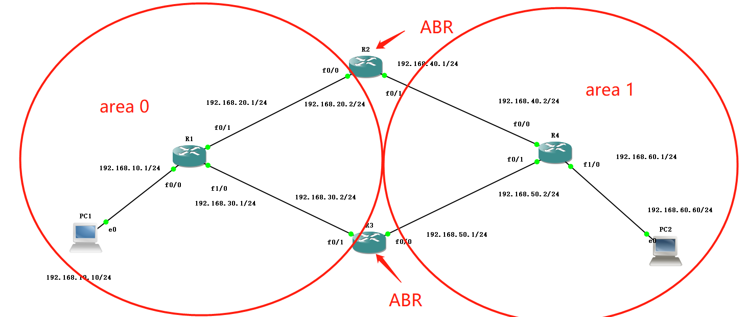
Dynamic routing-OSPF multi-area experimental configuration
1. Experimental environment GNS3 simulator (CRT terminal) Two VPCs (winpcap) Four C3725 routers (increased disk space) 2. Experimental purpose Enable PCs in different areas to communicate with each ot...

Dynamic routing OSPF single area configuration
Dynamic routing protocolOSPFSingle area network One,Basic configuration (omitted) two,interfaceIPConfiguration interfaceIPI won’t write more configuration commands, just configure as show...
Cisco Experiment 16. Network Layer: OSPF Routing Protocol (on)
Single area OSPF routing configuration experiment Basic knowledge Common command experiment process 1. Configure the host IP address 2. Configure the IP address of each port of the router. 3. Package ...