Sequence detector based on System Verilog
tags: FPGA IC related Digital IC design
This article realizes a 10010 sequence detector through System Verilog
Status machine design
The state machine is a very important concept in digital circuit design. Many complex controls can be completed through the state machine. The 10010 sequence detector to be realized in this article can also be achieved through the state machine.
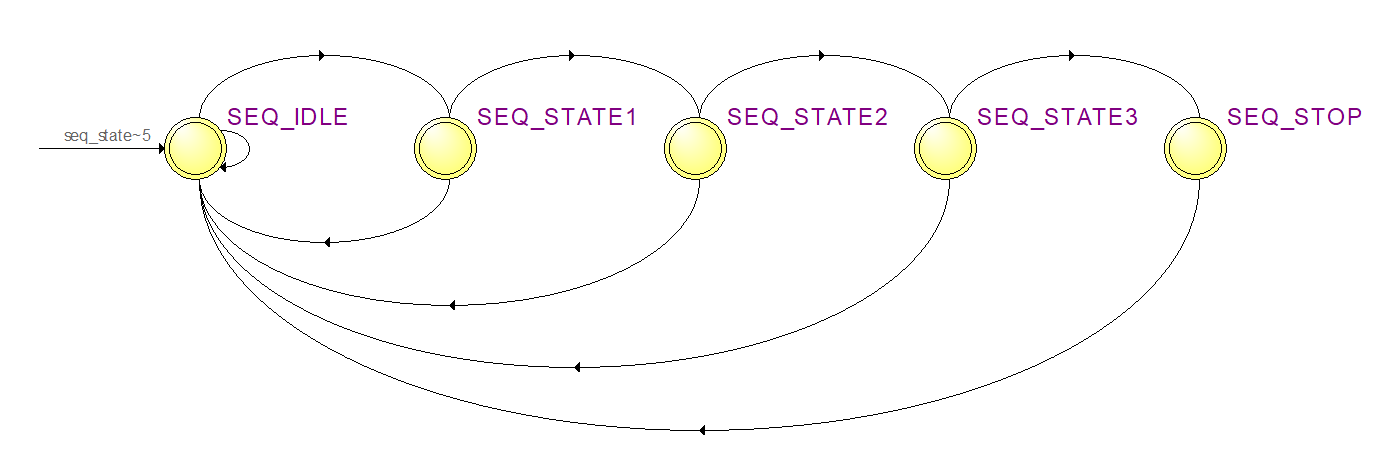
The following is the idea of the design machine design:
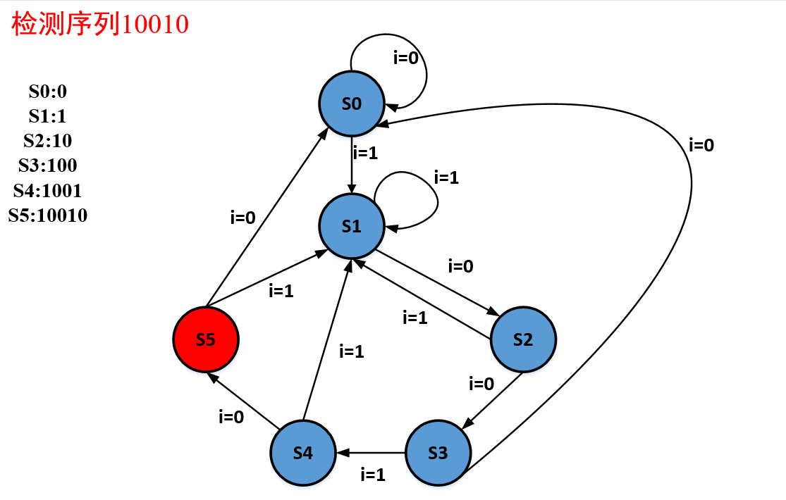
S0 means the current detected sequence is 0. If 1 is detected, it will be converted to S1, otherwise the original state will remain unchanged;
S1 means that the current detected sequence is 1. If 1 is detected, the state is kept unchanged. If 0 is detected, jump to the status S2;
S2 means that the current detection sequence is 10. If 1 is detected, jump to S1, otherwise jump to S3;
S3 indicates that the currently detected sequence is 100. If 1 is detected, jump to S4, otherwise jump to S0;
S4 means that the currently detected sequence is 1001. If 0 is detected, jump to S5, otherwise jump to S1.
S5 means the current detected sequence is 10010. If 0 is detected, jump to S0, otherwise it will jump to S1
The state machine is shown in the figure below:
RTL implementation
`timescale 1ns / 1ps
//
// Company:
// Engineer:
//
// Create Date: 2022/02/23 13:50:20
// Design Name:
// Module Name: Sequence_detection
// Project Name:
// Target Devices:
// Tool Versions:
// Description:
//
// Dependencies:
//
// Revision:
// Revision 0.01 - File Created
// Additional Comments:
//
//


module Sequence_detection(
input logic clk,
input logic rst,
input logic bit_in,
output logic detected
    );

typedef enum bit [2:0]
{
S0,
S1,
S2,
S3,
S4,
S5}
FSM_STATE;
//
FSM_STATE cur_state,next_state;
always_ff@(posedge clk,posedge rst)
if(rst)
    cur_state<=S0;
else
    cur_state<=next_state;
//
always_comb
begin
    case(cur_state)
        S0:if(bit_in)
               next_state=S1;
           else
               next_state=S0;
        S1:if(bit_in)
               next_state=S1;
           else
               next_state=S2;           //10
        S2:if(bit_in)
               next_state=S1;
            else
               next_state=S3;           //100
        S3:if(bit_in)
               next_state=S4;            //1001
            else
               next_state=S0;
        S4:if(bit_in)
                next_state=S1;
            else
                next_state=S5;           //10010
        S5:if(bit_in)
                next_state=S1;
            else
                next_state=S0;
        default:next_state=S0;
    endcase
end
//
assign detected=(cur_state==S5)?1'b1:1'b0;
endmodule
Test platform, use random numbers to generate input sequences
`timescale 1ns / 1ps
//
// Company:
// Engineer:
//
// Create Date: 2022/02/23 14:00:13
// Design Name:
// Module Name: test_tb
// Project Name:
// Target Devices:
// Tool Versions:
// Description:
//
// Dependencies:
//
// Revision:
// Revision 0.01 - File Created
// Additional Comments:
//
//


module test_tb;
logic clk;
logic rst;
logic bit_in;
logic detected;
initial begin
    clk=0;
    forever begin
        #5 clk=~clk;
    end
end
initial
begin
    rst=1;
    #20
    rst=0;
end
//
always_ff@(posedge clk,posedge rst)
if(rst)
    bit_in<=0;
else
    bit_in<=$random%2;

Sequence_detection U(.*);
// input logic clk,
// input logic rst,
// input logic bit_in,
// output logic detected
//     );
endmodule
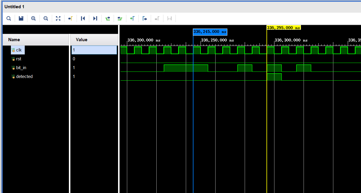
Simulation waveforms:
Intelligent Recommendation

Design of verilog-"10101" state machine sequence detector
First, draw a state transition diagram Code: Test code: Simulation results: The more you are, the more you have to work hard....

Verilog implementation of "10010" sequence detector and Modelsim simulation
The sequence detector is one of the very common designs in sequential digital circuits. Its main function is to identify a specified sequence from the digital code stream.For example, after receiving ...
Revisit the FPGA sequence detector verilog implementation
1. Title 2. Source code Three-stage state machine 3. Testing platform 4. Simulation waveform ...
Verilog implements FSM (Sequence Detector 1101)
Introduction: Verilog uses a finite state machine to implement a 1101 (overlapping) sequence detector, focusing on the practice of the three-stage coding style of the finite state machine. Code: Model...
Verilog - Sequence Modular Three (Divisible by 3) Detector
Verilog-Sequence Modular Three (Divisible by 3) Detector Description: The input port is 1bit, one bit of data comes in each time, check whether the current sequence can divide 3 evenly, output 1 if it...
More Recommendation
Verilog - Sequence Detector (implemented by shift register)
Transfer from: https://www.cnblogs.com/qiweiwang/archive/2011/04/18/2019952.html Verilog-sequence detector (implemented by shift register) The sequence detector is to identify a specified sequence fro...
Verilog - parallel 2bit input sequence detector
Verilog-Parallel 2bit input sequence detector @(verilog) Espressif 2020 Written Exam Questions: Description: The input port of the module is parallel 2bit to realize the ( 1011001 ) 2 (1011001)_2 (101...
[Original] "1101 Sequence Detector" written in Verilog
Sequence detector is one of the very common designs in sequential digital circuits. Its main function isIdentify a specified sequence from the digital code stream. Here is a Verilog implementation and...
Prepare the Verilog sequence detector code for autumn tricks
Detect 10010 sequence ...

Verilog Sequence Detector State Machine Register Writing
State machine writing Ability to detect overlapping portions Register writing: the difference The shift register needs to store all codewords, so if the sequence length is n, the method needs to consu...