USB application examples of stm32 (self-made simple mouse device, detailed source code)
Preface:Most of the stm32 products carry a USB2.0 full-speed peripheral and provide a USB development library; we can use the development library to develop some USB devices, such as audio devices, mass storage devices, printers, human-machine interface devices, etc. The reason why the PC can identify different plug-in devices is because USB has developed a set of standard protocols. After the USB device is inserted, the host will query the device information. After the device information is inquired, the host itself queries the matching driver and loads the driver. The application in the computer can use the device. The following will use the routine of the usb library provided by st official website to rewrite the routine to make a usb mouse device, and control the movement of the mouse cursor through a joystick connected to the stm32 development board.
1. Hardware design:
- A minimum system development board for stc32f103c8t6
- One rocker sensor
- USB-mrico cable, several Dupont cables, J-LINK downloader
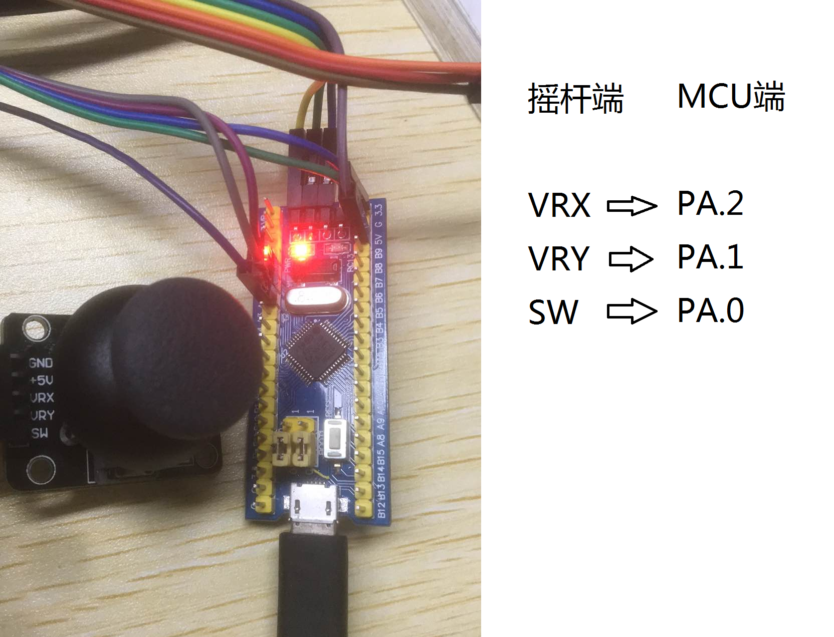
The wiring is shown in the figure above. The rocker sensor and MCU need to be connected to the same power supply 3.3v.
2. Software design:
1. Programming points:
1. Use the stm32 standard library to perform AD collection; obtain the movement of the joystick by detecting the voltage of the pin of the joystick. The principle of the joystick is to change the resistance of the potential when shaking, thereby changing the voltage.
2. Use the USB development library to understand the official <JoyStickMouse> project routines.
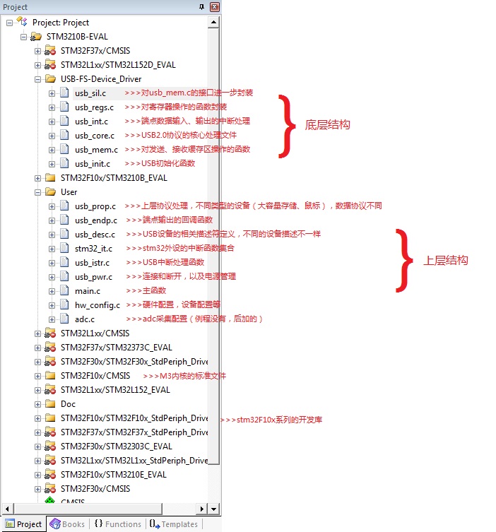
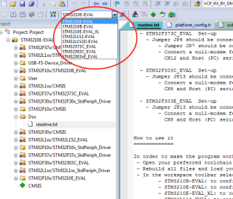
First, briefly explain the project files of the official routines, download resources from the official website and configure the project, you can refer tolink, Select the JoyStickMouse project to open, although you see many files, but many of them are useless to participate in compilation, the structure is as follows:
2. Code design:
The official code compilation can be used, but the hardware configuration is not what we want, so we need to change some; first, this official routine is to simulate the up and down, left and right movement of the mouse through 4 buttons, and the button will move a certain amount every time you press it. The distance of mcu here is to send the mouse's movement information (such as how much the x-axis has moved, etc.) to the host via 4 bytes, then the host responds by analyzing the received data; in fact, every data is a host Only when the inquiry is initiated, the MCU responds.
We need to remove the official button part. The mouse movement information is simulated by the joystick sensor. Then, the joystick sensor is first detected by ad voltage to detect the movement in 4 directions, and then the response data is sent to the host.
- >>>Create adc.h
#ifndef __ADC_H
#define __ADC_H
#include "platform_config.h"
#include <stdio.h>
/*
 #define ADC_CH0 0 //Channel 0
 #define ADC_CH1 1 //Channel 1
 #define ADC_CH2 2 //Channel 2
 #define ADC_CH3 3 //Channel 3
*/
void Adc_GPIO_Config(void);
void Adc_Config(void);
#endif - >>>Create adc.c
#include "adc.h"
volatile u16 ADC_ConvertedValue[10][3];
void Adc_GPIO_Config(void)
{
GPIO_InitTypeDef GPIO_InitStructure;
/*Enable GPIO and ADC1 channel clock*/
RCC_APB2PeriphClockCmd(RCC_APB2Periph_GPIOA |RCC_APB2Periph_ADC1 , ENABLE );
/*Set PA0 as analog input*/
GPIO_InitStructure.GPIO_Pin = GPIO_Pin_2;
/*Set GPIO as analog input*/
GPIO_InitStructure.GPIO_Mode = GPIO_Mode_AIN;
GPIO_Init(GPIOA, &GPIO_InitStructure);
GPIO_InitStructure.GPIO_Pin = GPIO_Pin_0;
/*Set GPIO as analog input*/
GPIO_InitStructure.GPIO_Mode = GPIO_Mode_AIN;
GPIO_Init(GPIOA, &GPIO_InitStructure);
GPIO_InitStructure.GPIO_Pin = GPIO_Pin_1;
/*Set GPIO as analog input*/
GPIO_InitStructure.GPIO_Mode = GPIO_Mode_AIN;
GPIO_Init(GPIOA, &GPIO_InitStructure);
}
void Adc_Config(void)
{
ADC_InitTypeDef ADC_InitStructure;
DMA_InitTypeDef DMA_InitStructure;
Adc_GPIO_Config();
/*72M/6=12, the maximum ADC time cannot exceed 14M*/
RCC_ADCCLKConfig(RCC_PCLK2_Div6);
/*Reset all registers of peripheral ADC1 to default values*/
ADC_DeInit(ADC1);
/*ADC working mode: ADC1 and ADC2 work in independent mode*/
ADC_InitStructure.ADC_Mode = ADC_Mode_Independent;
/*Analog to digital conversion works in single channel mode*/
ADC_InitStructure.ADC_ScanConvMode = ENABLE;
/*Analog to digital conversion works in single conversion mode*/
ADC_InitStructure.ADC_ContinuousConvMode = ENABLE;
/*ADC conversion is started by software instead of external trigger*/
ADC_InitStructure.ADC_ExternalTrigConv = ADC_ExternalTrigConv_None;
/*ADC data right aligned*/
ADC_InitStructure.ADC_DataAlign = ADC_DataAlign_Right;
/*Number of ADC channels for regular conversion in sequence*/
ADC_InitStructure.ADC_NbrOfChannel = 3;
/*Initialize the register of the peripheral ADCx according to the parameters specified in ADC_InitStruct*/
ADC_Init(ADC1, &ADC_InitStructure);
ADC_RegularChannelConfig(ADC1, ADC_Channel_0, 1, ADC_SampleTime_239Cycles5 );
ADC_RegularChannelConfig(ADC1, ADC_Channel_1, 2, ADC_SampleTime_239Cycles5 );
ADC_RegularChannelConfig(ADC1, ADC_Channel_2, 3, ADC_SampleTime_239Cycles5 );
/*Enable the specified ADC1*/
ADC_Cmd(ADC1, ENABLE);
ADC_DMACmd(ADC1, ENABLE);
/*Reset the calibration register of the specified ADC1*/
ADC_ResetCalibration(ADC1);
/*Get the status of ADC1 reset calibration register, and wait for setting status*/
while(ADC_GetResetCalibrationStatus(ADC1));
/*Start the calibration of the specified ADC1*/
ADC_StartCalibration(ADC1);
/*Get the calibration program of the specified ADC1, and wait for the setting state*/
while(ADC_GetCalibrationStatus(ADC1));
RCC_AHBPeriphClockCmd(RCC_AHBPeriph_DMA1, ENABLE);
DMA_InitStructure.DMA_PeripheralBaseAddr = (u32)&(ADC1->DR);
DMA_InitStructure.DMA_MemoryBaseAddr =(u32)&ADC_ConvertedValue;
DMA_InitStructure.DMA_DIR = DMA_DIR_PeripheralSRC;
DMA_InitStructure.DMA_BufferSize = 30;
DMA_InitStructure.DMA_PeripheralInc = DMA_PeripheralInc_Disable;
DMA_InitStructure.DMA_MemoryInc = DMA_MemoryInc_Enable;
DMA_InitStructure.DMA_PeripheralDataSize = DMA_PeripheralDataSize_HalfWord;
DMA_InitStructure.DMA_MemoryDataSize = DMA_MemoryDataSize_HalfWord;
DMA_InitStructure.DMA_Mode = DMA_Mode_Circular;
DMA_InitStructure.DMA_Priority = DMA_Priority_High;
DMA_InitStructure.DMA_M2M = DMA_M2M_Disable;
DMA_Init(DMA1_Channel1, &DMA_InitStructure);
DMA_Cmd(DMA1_Channel1,ENABLE);
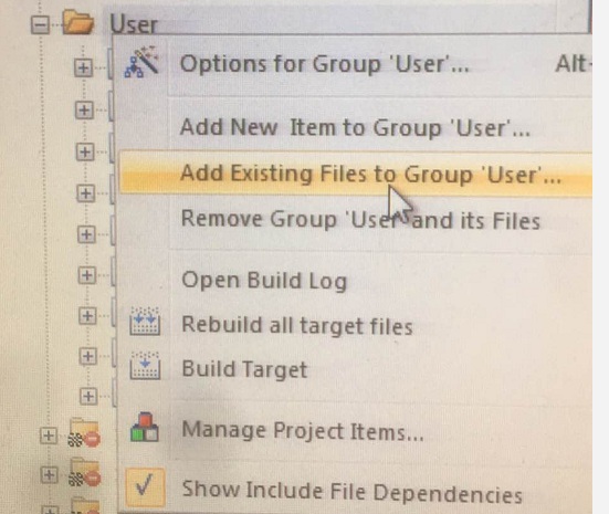
}After the above two are written, copy them to the inc and src folders under the JoyStickMouse directory. Add the adc.c file and stm32f10x_adc.c to the project, the latter is under STM32_USB-FS-Device_Lib_V4.1.0\Libraries\STM32F10x_StdPeriph_Driver\src, because the official routine does not use adc, so this file is not added in the official project. The operation of adding the c file to the project is shown in the figure, click and find the file to be added:
- >>>Add include "adc.h" in main.c, and then call the following two functions after ""USB_Init();" in the main function:
	Adc_Config();
	ADC_SoftwareStartConvCmd(ADC1, ENABLE);
At this point, the ad collection has been configured, and the voltage values of PA.0, PA.1, and PA.2 will be automatically collected into the ADC_ConvertedValue[10][3] array. Each channel collects 10 values at a time and takes the average. Then the next step is to remove the button configuration of the official routine, and judge the rocking direction of the joystick according to the value of ADC_ConvertedValue[10][3].
- >>>Remove the useless button initialization, find the following code in hw_config.c and comment it out:
 /*
  STM_EVAL_PBInit(Button_RIGHT, Mode_GPIO);
  STM_EVAL_PBInit(Button_LEFT, Mode_GPIO);
  STM_EVAL_PBInit(Button_UP, Mode_GPIO);
  STM_EVAL_PBInit(Button_DOWN, Mode_GPIO);
*/- >>>Find in the main function:
    if ((JoyState() != 0) && (PrevXferComplete))
    {
         Joystick_Send(JoyState());
    }
 Replace with:
    if(PrevXferComplete){
                 JoyState();//Continue to use the original function name, wait for the function to be found, and change the content inside
    }
PrevXferComplete is the sign of the completion of the last interaction. Wait until the last interaction is over. The JoyState() function will be changed to detect the state of the joystick sensor and send the state information, as follows.
#if 0
uint8_t JoyState(void)
{
//Original code slightly...
}
#else //Rewrite the JoyState function
extern volatile u16 ADC_ConvertedValue[10][3];
u16 ConvertedValue[3];
void get_Average(void)//Average
{
u8 i,j;
int sum;
for(i=0;i<3;i++){
sum=0;
for(j=0;j<10;j++){
sum+=ADC_ConvertedValue[j][i];
}
ConvertedValue[i]=sum/10;
}
}
#define middle_x 0x07e2
#define middle_y 0x0813
#define idle_press 0x07cd
/*******************************************************************
Note: If the 12-bit adc converter is used, the maximum conversion value is 0xFFF, and the corresponding voltage is up to 3.3v;
The minimum conversion value is 0, and the corresponding voltage is 0v; so the relationship between the voltage value and the conversion value is obvious. Of course, there is no
Need to calculate the voltage value. The values of middle_x, middle_y, idle_press are the static detection values of the joystick, I deliberately
When printed, the static value of different originals may be different. Their value is probably in the middle of 0~0xFFF, shake up and down
Control a potentiometer, shake to control a potentiometer, so it is reasonable to detect the intermediate value when it is static
, And then determine the change trend of the detected value relative to the static detected value to know the direction of shaking.
*********************************************************************/
uint8_t JoyState(void)
{
uint8_t Mouse_Buffer[4] = {0, 0, 0, 0}; //Mouse_Buffer[4] data format description see the next paragraph
int8_t X = 0, Y = 0;
uint8_t temp1,temp2;
get_Average();
/*Calculate the offset of the X coordinate*/
temp1=(ConvertedValue[0]&0xF00)>>8;
if(temp1<7){ //to the left
X=temp1-7;
}else if(temp1>8){ //to the right
X=temp1-8;
}
/*Calculate the offset of the Y coordinate*/
temp2=(ConvertedValue[1]&0xF00)>>8;
if(temp2<7){ //Down
Y=temp2-7;
}else if(temp2>8){ //up
Y=temp2-8;
}
/*Determine the state of the SW button*/
if(ConvertedValue[2]<0x200){
Mouse_Buffer[0]=0x01; //Left mouse click
}
/* prepare buffer to send */
Mouse_Buffer[1] = X;
Mouse_Buffer[2] = Y;
/* Reset the control token to inform upper layer that a transfer is ongoing */
PrevXferComplete = 0;
/* Copy mouse position info in ENDP1 Tx Packet Memory Area*/
USB_SIL_Write(EP1_IN, Mouse_Buffer, 4);
/* Enable endpoint for transmission */
SetEPTxValid(ENDP1);
return 0;
}
#endifThe information sent by the device to the host is stored in the four bytes of Mouse_Buffer[4]:
Mouse_Buffer[0]--
|--bit7~bit3:
|--bit2: 1 means middle button is pressed
|--bit1: 1 means right click
|--bit0: 1 means that the left button is pressedMouse_Buffer[1]-X coordinate change amount, negative number means moving to the left, positive number means moving to the right. Use complement to express the amount of change
Mouse_Buffer[2]-- Y coordinate change amount, negative number means move down, positive number means move up. Express the amount of change in complement
Mouse_Buffer[3]-- scroll wheel changes, negative number means scroll up, negative number means scroll down
3. Download verification:
Compile the modified project, connect the J-LINK downloader, and burn the program into the development board; connect the development board to the computer via USB-mrico, the computer will automatically identify the device and load the corresponding driver; After waiting for a period of time, you can observe that the mouse cursor is moving by shaking the joystick, and the greater the shaking, the faster the cursor moves; otherwise, the slower; if shaking the joystick has no response, check whether the line is well connected; In addition, the static ad conversion value of the joystick can be sent through the serial port. Of course, you need to configure the usart peripheral, then use the serial port assistant to receive the value on the computer.
The problem encountered: When the J-LINK is not unplugged and the USB-mrico is connected to the development board, the development board device cannot be recognized; I had to unplug the J-LINK first. This reason is temporarily unknown, it may be my computer.
So far, the self-made mouse device has been completed; if you want to further understand the official <JoyStickMouse> routine, please refer toBaidu Library。
The level is limited, it is for reference only, and I hope you can advise me on the errors and deficiencies.
Intelligent Recommendation
USB application examples of stm32 (download and use of official routine data)
Development environment: Window 7 Development tool: Keil uVision5 Hardware: stc32f103c8t6 Many stm32 series chips have a USB2.0 full-speed communication interface. The following describes how to use s...

USB mouse driver source code analysis
kernel:kernel-3.4.39 UHCI: intel, Low speed (1.5Mbps) / full speed (12Mbps) OHCI: microsoft Low speed / full speed EHCI: High speed (480Mbps) USBThe role of the bus driver: 1Assign the ad...
The STM32 USB program source code analysis JoyStickMouse
The STM32 USB program source code analysis JoyStickMouse A, USB's "JoyStickMouse" routine structural analysis 1, the structure of the routine (1) substructure Includes five files: usb_core.c...
STM32 USB program JOYSTICKMOUSE source code analysis
https://my.oschina.net/u/184090/blog/467826 I. Analysis of USB's "JoyStickMouse" routine 1, the structure of routine (1) Bottom structure Including 5 files: USB_CORE.C (...
"Operating System Truth Restore" From Zero Self-made Operating System Self-write Source Code (Device Related Files)
Article catalog Column blog link Device related files Written console.c Written console.h Written Ide.c Written Ide.h Ioqueue.c written Ioqueue.h written Compared to Keyboard.c Compared to Keyboard.h ...
More Recommendation
C8051 USB Device : Modify the MouseExample Code as UART-Input Mouse.
I found the example code of silicon labs's MouseExample is not explicit: the input signal is from analog to digital converter (ADC) pin: it ...
Generic self-made examples
[quote] CallMan to make a call, a bit mimicking the pattern of jdbcTemplate, the data format type returned by the client [/quote] [code] package com.ssc.dbcttool.generic; public interface Nail<T>...
STM32 study notes - USB mouse
The STM32 simulates USB mouse that has been done for a long time recently, and its function is to simply use three buttons to realize the functions of the scroll wheel and left and right mouse buttons...

Implementation of Self-made USB Device Supervision System Based on USBDeview (1)——System Architecture
Nowadays, enterprises are paying attention to information security in information systems, and the supervision of mobile devices with USB interfaces is becoming more and more strict. There are many pl...
Implementation of Self-made USB Device Supervision System Based on USBDeview (4)——Guard Process
The Guard Process is a daemon that prevents users from intentionally or inadvertently terminating the resident usbdeview process. In this article, the daemon is named USB Monitor Service (hereafter re...