Calculation of clock frequency of stm32 timer
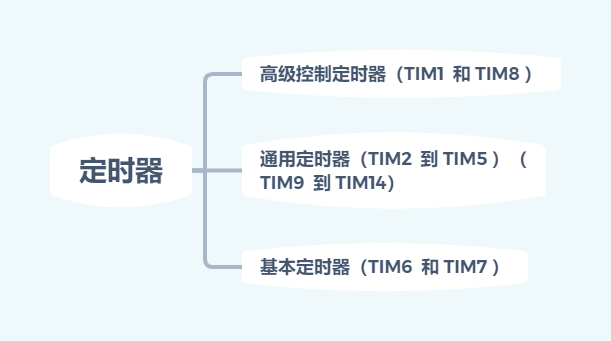
Basic introduction to stm32 timer
f4:
stm32 timer clock frequency
| System clock | Frequency/MHZ |
|---|---|
| SYSCLK (system clock) | 168 |
| APB1 bus clock (divided by 4) | 42 |
| APB2 bus clock (divide by 2) | 84 |

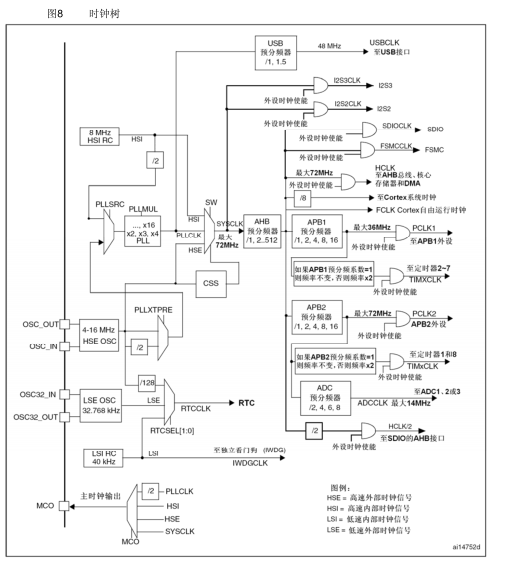
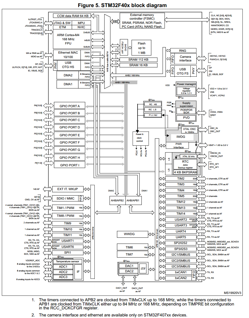
Because the system initialization SystemInit function has initialized the clock of APB1 to divide by 4, the clock of APB1 is 42M, and from the internal clock tree diagram of STM32F4 (above):
(1) When the clock division number of APB1 is 1, the clocks of TIM2~7 and TIM12~14 are the clocks of APB1.
(2) And if the clock division number of APB1 is not 1, then the clock frequency of TIM2~7 and TIM12~14 will be twice the clock frequency of APB1
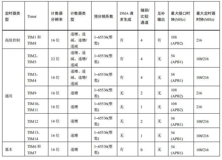
It should also be noted here that the advanced timers and the clocks of TIM9~TIM11 are not coming
is from APB1, but from APB2. (The clock frequency of the timer is similar to APB1)
| Timer clock | frequency |
|---|---|
| TIM1、TIM8–11 | 2*APB2 |
| TIM2—7、TIM12—14 | 2*APB1 |
Calculation of timer overflow time:
Tout= ((arr+1)*(psc+1))/Tclk;
where:
Tclk: TIM input clock frequency (unit is hz).
Tout: TIM overflow time (unit: s).
E.g:
Timer 3 as an example
  void TIM3_Int_Init(u16 arr,u16 psc)
  {
      TIM_TimeBaseInitTypeDef TIM_TimeBaseInitStructure;
      NVIC_InitTypeDef NVIC_InitStructure;
      RCC_APB1PeriphClockCmd(RCC_APB1Periph_TIM3,ENABLE); //①Enable TIM3 clock
             TIM_TimeBaseInitStructure.TIM_Period = arr; //Automatic reload value
             TIM_TimeBaseInitStructure.TIM_Prescaler=psc; //Timer division
	 TIM_TimeBaseInitStructure.TIM_CounterMode=TIM_CounterMode_Up; //Up counting mode
	TIM_TimeBaseInitStructure.TIM_ClockDivision=TIM_CKD_DIV1;
	 TIM_TimeBaseInit(TIM3,&TIM_TimeBaseInitStructure);// ②Initialize the timer TIM3
	 TIM_ITConfig(TIM3,TIM_IT_Update,ENABLE); //③Allow timer 3 update interrupt
	 NVIC_InitStructure.NVIC_IRQChannel=TIM3_IRQn; //Timer 3 interrupt
	 NVIC_InitStructure.NVIC_IRQChannelPreemptionPriority=0x01; //Preemption priority 1
	 NVIC_InitStructure.NVIC_IRQChannelSubPriority=0x03; //Response priority 3
	NVIC_InitStructure.NVIC_IRQChannelCmd=ENABLE;
	 NVIC_Init(&NVIC_InitStructure);// ④Initialize NVIC
	 TIM_Cmd(TIM3,ENABLE); //⑤Enable timer 3
  }
Call the function TIM3_Int_Init(5000-1,8400-1) in the main function;
Its overflow time is calculated as follows:
The timer clock is 84M, the frequency division factor is 8400, so 84M/8400=10Khz counting frequency, counting 5000 times is 500ms.
Intelligent Recommendation
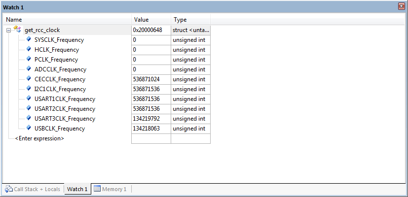
STM32 measurement system clock frequency
Create a project and enter in the main function: The RCC_GetClocksFreq function can be found in stm32fxxrcc.h of the library function. Download to the development board, you can view the frequency val...
STM32-04 - Modify Clock Frequency
table of Contents New board support package Add the .C file to the User under the project file and configure the path to the .h folder in the magic rod (like 03) Write the .c file and .h file accordin...

stm32 clock tree and modify the system clock frequency
Foreword: When learning 51, we know that the microcontroller must have a clock to work. In stm32, an external clock source is not necessary, because there is a clock source internally, so we need to u...
STM32 clock introduction and system clock frequency change
I. Clock source STM32 has 5 clock sources, namely: 1.Hse: high_speed_extenal External High Speed Clock, welding outside the chip, high precision, is the main source of system clock. 2.HSI: High_Spee...
STM32 study notes (a) clock and timer
Due to the recent preparations for the marine craft competition, I just took the opportunity to learn about ARM and see that many students around are using 32, so I also bought a piece of STM32F103ZET...
More Recommendation
STM32 timer using (a) a timing clock
Timer Category 1, the basic timer TIM6, TIM7; timer can generate an interrupt, no input and output pins; 2, General timer TIM2, TIM3 / TIM4 / TIM5; timer interrupt, compare / capture, the PWM square w...
STM32 clock timer doubt understanding
Some understanding of the problems encountered. The TIM_Period of the clock timer can be set to the auto-reload value. After the interrupt is triggered, the auto-reload value can continue to count, an...
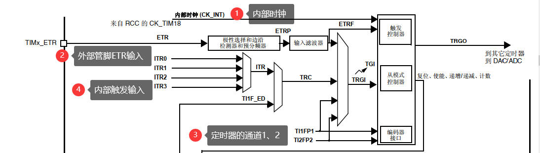
STM32 advanced timer clock source
1. Block diagram of timer clock source You can see from the picture that the timer has 4 clock sources, (1) Internal clock; (2) External clock mode 1, timer channel 1, 2; (3) External clock mod...
STM32 timer clock configuration skills
Well-known The clock configuration of STM32 is more complicated, and the timer's clock configuration is more 'wonderful'. As shown below (Screenshot Since the STM32F4 Programming Manual) APB's pre-pro...
STM32 F7 timer PWM output and input capture related frequency calculation formula finishing
The project is used Want to make a memo Frequency supported by timer By default, according to the maximum interface clock frequency * 2 For special cases, please see this register Do ordinary timing f...