Verilog implementation of CRC check algorithm
1. Brief description of the article
The CRC algorithm has a wide range of applications in the field of communication and data transmission. The principle of CRC will not be explained in this document. This document will focus on the use of Verilog CRC code generation tools and how to Modify the code to meet our requirements and explain the implementation of the CRC algorithm in Verilog. This tutorial covers the following aspects:
1. Introduction to CRC type
2. Introduction to CRC parameters
3. Use of crc-gen code production tool
4. Transplantation of CRC verification code
5. CRC check code test
2. Introduction to the parameters in the CRC algorithm
2.1 CRC type
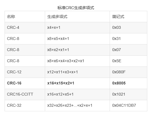
In short, CRC is divided into CRC-4, CRC-5, CRC-6, CRC-7, CRC-8, CRC-16, CRC-32; however, it can be modified. The detailed classification is shown in Figure 1. The same is CRC-8 but there are four different calculation methods, such as CRC-8, CRC-8/ITU, CRC-8/ROHC, CRC-8/MAXIM. Therefore, when performing CRC inspection, the selection should be made according to the actual situation, and the verification method must be consistent when the two parties communicate.
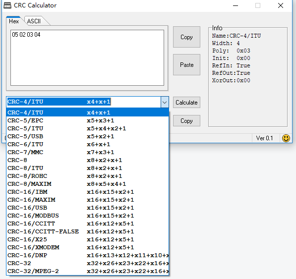
Figure 1 CRC type diagram
2.2 CRC parameters:
It can be seen from Figure 1 that each type of CRC has multiple parameters. This parameter is used to determine how the verification algorithm is implemented, as shown in Figure 2.
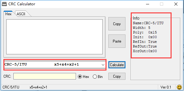
Figure 2 CRC parameter diagram
CRC Name: The name of the CRC algorithm, which is also a very important parameter in the use of CRC verification. It is meaningful for both parties to use the same verification method for verification and comparison during use.
CRC Width: The bit width of the CRC output result, which corresponds to -X in the CRC name.
CRC Poly: This parameter is the core parameter of CRC check, it is related to CRC check formula. For example: the formula of CRC-5/ITC is x5+x4+x2+1, which is equivalent to x5×1+x4×1+x3×0+x2×1+x1×0+x0×1, which is expressed in binary Order relationship: 10101 (the highest order must be removed), 10101 in binary is equal to 0x15 in sixteen. Similarly, other tests of Poly can also be determined in the same way.
CRC Init: This parameter is the initial value of the CRC check result.
CRC RefIn: This parameter determines whether the input data is byte inverted, if it is true, it needs to be inverted, if it is false, it does not need to be inverted.
CRC RefOut: This parameter determines whether the CRC preliminary check result is to be reversed in bytes, if it is true, it needs to be reversed, if it is false, it does not need to be reversed.
CRC XorOut: This parameter determines the Xor value when the CRC check result is output.
2.3 Understanding of the CRC inspection process:
Regarding CRC check, my understanding is that, first of all, there is a most basic CRC algorithm, which is the backbone of CRC. The parameters it needs are Width, Poly, Init; and some Peripheral algorithms, such as whether the input and output are reversed, the output result needs the value of XOR, its parameters include: RefIn, RefOut, XorOut.
Third, the use of CRC algorithm Verilog code production tool
3.1 Introduction to crc-gen tool
crc-gen is a crc verification code generation tool based on command line operation, which can generate the basic code of CRC algorithm in VHDL and Verilo HDL languages. After generating the basic code, we only need to modify the parameters according to the parameter requirements of the CRC check algorithm we use, and then we can write the VHDL or Verilog HDL code that meets the required CRC check. What I study is Verilog HDL language, this article will explain in this language.
The Crc-gen tool can be downloaded from the Internet, or you can use the link below to download it.
crc-gen download link: https://pan.baidu.com/s/1BuH7LmCB7x2gd1tJAuPCYA
Extraction code: rt2z
3.2 Use of crc-gen
Before using it, please take a look at the documentation in the crc-gen folder. So as not to understand the following operations. This example uses the CRC-8/MAXIM check method, and the CRC polynomial is: x8+x5+x4+1.
First, open the computer cmd command line and enter the crc-gen folder, as shown in Figure 3:
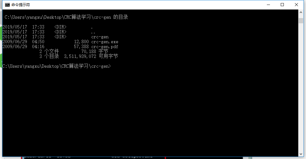
Figure 3 crc-gen initial interface
The command format of crc-gen is as follows:
crc-gen language data_width poly_width poly_string
language: verilog or vhdl
data_width: data width, 1-1024.
poly_width: CRC polynomial width, 1-1024.
poly_string: CRC polynomial description, that is, CRC Poly parameters, expressed in hexadecimal.
The polynomial of CRC-8/MAXIM is x8+x5+x4+1, and the polynomial value can be obtained as 0x31. The code we want to generate, the programming language uses Verlog, the data input is 8 bits, enter the following command:
crc-gen Verilog 8 8 31, as shown in Figure 4:
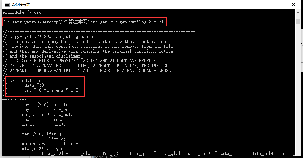
Figure 4 crc-gen command input and code generation interface
It can be seen from the figure that the CRC code has been generated, and the formula is consistent with the formula we require.
Assign the code to the file, the copied code is as follows:
// CRC module for
//       data[7:0]
//       crc[7:0]=1+x^4+x^5+x^8;
//
module crc(
        input [7:0] data_in,
        input        crc_en,
        output [7:0] crc_out,
        input        rst,
        input        clk);

        reg [7:0] lfsr_q,
                   lfsr_c;
        assign crc_out = lfsr_q;
        always @(*) begin
                lfsr_c[0] = lfsr_q[0] ^ lfsr_q[3] ^ lfsr_q[4] ^ lfsr_q[6] ^ data_in[0] ^ data_in[3] ^ data_in[4] ^ data_in[6];
                lfsr_c[1] = lfsr_q[1] ^ lfsr_q[4] ^ lfsr_q[5] ^ lfsr_q[7] ^ data_in[1] ^ data_in[4] ^ data_in[5] ^ data_in[7];
                lfsr_c[2] = lfsr_q[2] ^ lfsr_q[5] ^ lfsr_q[6] ^ data_in[2] ^ data_in[5] ^ data_in[6];
                lfsr_c[3] = lfsr_q[3] ^ lfsr_q[6] ^ lfsr_q[7] ^ data_in[3] ^ data_in[6] ^ data_in[7];
                lfsr_c[4] = lfsr_q[0] ^ lfsr_q[3] ^ lfsr_q[6] ^ lfsr_q[7] ^ data_in[0] ^ data_in[3] ^ data_in[6] ^ data_in[7];
                lfsr_c[5] = lfsr_q[0] ^ lfsr_q[1] ^ lfsr_q[3] ^ lfsr_q[6] ^ lfsr_q[7] ^ data_in[0] ^ data_in[1] ^ data_in[3] ^ data_in[6] ^ data_in[7];
                lfsr_c[6] = lfsr_q[1] ^ lfsr_q[2] ^ lfsr_q[4] ^ lfsr_q[7] ^ data_in[1] ^ data_in[2] ^ data_in[4] ^ data_in[7];
                lfsr_c[7] = lfsr_q[2] ^ lfsr_q[3] ^ lfsr_q[5] ^ data_in[2] ^ data_in[3] ^ data_in[5];


        end // always

        always @(posedge clk, posedge rst) begin
                if(rst) begin
                        lfsr_q  <= {8{1'b1}};
                end
                else begin
                        lfsr_q  <= crc_en ? lfsr_c : lfsr_q;
                end
        end // always
endmodule // crc
Four, Verilog code transplantation and modification
4.1 Parameter requirements
The parameters of CRC-8/MAXIM are shown on the right side of Figure 5, where Poly is 0x31, and the initial value is 0x00. Input and output need to be reversed. The output value must be XORed 0x00 (equivalent No XOR). In the generated code, we need to set the initial value and reverse the data input and output.
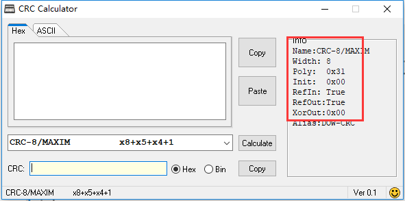
Figure 5 CRC-8/MAXIM parameters
4.2 Code modification
As can be seen from the parameters, we need to make three modifications (exclusive OR of the output result 0x00 is equivalent to no exclusive OR):
- The initial value of the CRC result, that is, the starting value of each CRC calculation, needs to be set to 0x00.
- The number of bits of the input data is reversed.
- Flip the output CRC check value.
The modified code is as follows:
// CRC module for
//       data[7:0]
//       crc[7:0]=1+x^4+x^5+x^8;
//
module crc(
        input [7:0] data_in,
        input        crc_en,
        output [7:0] crc_out,
        input        rst,
        input        clk);

        reg [7:0] lfsr_q,
                   lfsr_c;
		//The flip of input data
		/*
			 1. Define an 8-bit data
			 2. Flip data_in and assign it to data
			 3. Replace data_in in the always @(*) statement block with data
		*/
		wire [7:0]data;
		assign data = {data_in[0],data_in[1],data_in[2],data_in[3],data_in[4],data_in[5],data_in[6],data_in[7]};


		//The flip of output data
       assign crc_out = {lfsr_q[0],lfsr_q[1],lfsr_q[2],lfsr_q[3],lfsr_q[4],lfsr_q[5],lfsr_q[6],lfsr_q[7]};


        always @(*) begin
                lfsr_c[0] = lfsr_q[0] ^ lfsr_q[3] ^ lfsr_q[4] ^ lfsr_q[6] ^ data[0] ^ data[3] ^ data[4] ^ data[6];
                lfsr_c[1] = lfsr_q[1] ^ lfsr_q[4] ^ lfsr_q[5] ^ lfsr_q[7] ^ data[1] ^ data[4] ^ data[5] ^ data[7];
                lfsr_c[2] = lfsr_q[2] ^ lfsr_q[5] ^ lfsr_q[6] ^ data[2] ^ data[5] ^ data[6];
                lfsr_c[3] = lfsr_q[3] ^ lfsr_q[6] ^ lfsr_q[7] ^ data[3] ^ data[6] ^ data[7];
                lfsr_c[4] = lfsr_q[0] ^ lfsr_q[3] ^ lfsr_q[6] ^ lfsr_q[7] ^ data[0] ^ data[3] ^ data[6] ^ data[7];
                lfsr_c[5] = lfsr_q[0] ^ lfsr_q[1] ^ lfsr_q[3] ^ lfsr_q[6] ^ lfsr_q[7] ^ data[0] ^ data[1] ^ data[3] ^ data[6] ^ data[7];
                lfsr_c[6] = lfsr_q[1] ^ lfsr_q[2] ^ lfsr_q[4] ^ lfsr_q[7] ^ data[1] ^ data[2] ^ data[4] ^ data[7];
                lfsr_c[7] = lfsr_q[2] ^ lfsr_q[3] ^ lfsr_q[5] ^ data[2] ^ data[3] ^ data[5];


        end // always

		//Verify initialization
		/*
			 Change lfsr_q <= {8{1'b1}} in always @(posedge clk, posedge rst) to lfsr_q <= {8{1'b0}}.
		*/
        always @(posedge clk, posedge rst) begin
                if(rst) begin
                        lfsr_q  <= {8{1'b0}};
                end
                else begin
                        lfsr_q  <= crc_en ? lfsr_c: lfsr_q;
                end
        end // always
endmodule // crc
Five, testing and analysis
5.1 test code
Test input data bits 0x01, 0x02, 0x03, 0x04, the test code is as follows:
module CRC(
input CLK
);
	//Divide the clock for operation
	reg [1:0]cnt = 2'd0;
	reg CLK_DIV = 1'd0;
	always@(posedge CLK)
		begin
			if(cnt == 2'd3)
				begin
					CLK_DIV <= ~CLK_DIV;
					cnt <= 2'd0;
				end
			else
				begin
					cnt <= cnt + 1'd1;
				end
		end

	//Test the CRC module
	reg [7:0]crc_data_test[3:0];
	reg [7:0]crc_cnt = 8'd0;

	reg [7:0]crc_data_in;
	wire [7:0]crc_data_out;
	reg crc_en;
	reg crc_rst;
	//crc-8 instantiation
	crc(
        .data_in(crc_data_in),
        .crc_en(crc_en),
        .crc_out(crc_data_out),
        .rst(crc_rst),
        .clk(~CLK_DIV)
		  );

	//Test state machine
	always@(posedge CLK_DIV)
		begin
			case(crc_cnt)
				8'd0:
					begin
						//Assign initial value to test data
						crc_data_test[0] <= 8'h01;
						crc_data_test[1] <= 8'h02;
						crc_data_test[2] <= 8'h03;
						crc_data_test[3] <= 8'h04;
						//Close crc
						crc_en <= 1'd0;
						//Reset crc
						crc_rst <= 1'd1;
						//Increase the status counter by 1
						crc_cnt <= crc_cnt + 1'd1;
					end
				8'd1:
					begin
						//Enable crc
						crc_en <= 1'd1;
						//Stop resetting crc
						crc_rst <= 1'd0;
						//Input data initial value
						crc_data_in <= crc_data_test[0];
						//Increase the status counter by 1
						crc_cnt <= crc_cnt + 1'd1;
					end
				8'd2:
					begin
						//Input data initial value
						crc_data_in <= crc_data_test[1];
						//Increase the status counter by 1
						crc_cnt <= crc_cnt + 1'd1;
					end
				8'd3:
					begin
						//Input data initial value
						crc_data_in <= crc_data_test[2];
						//Increase the status counter by 1
						crc_cnt <= crc_cnt + 1'd1;
					end
				8'd4:
					begin
						//Input data initial value
						crc_data_in <= crc_data_test[3];
						//Clear the status counter
						crc_cnt <= 8'd0;
					end
				default:
					begin
						crc_cnt <= 8'd0;
					end
			endcase
		end
endmodule
5.2 Test results
CRC computer calculation results are shown in Figure 6.
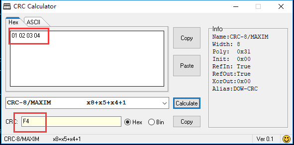
Figure 6 CRC computer calculation results
FPGA test results are shown in Figure 7.
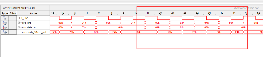
Figure 7 FPGA test results
As can be seen from the figure, when the input data is the same, after the data input, the CRC check output value is the same as the result calculated by the CRC calculator.
Intelligent Recommendation
Python implementation of crc check
Crc (Cyclic Redundancy Check): Cyclic Redundancy Check is a commonly used error checking code. The essence is to append a checksum (both in binary sequence) to the message to be sent. Implementation s...
Implementation of CRC check method
1. Determine the check digit used by the sender and receiver (customized by the sender and receiver) For example, 1 byte is CRC-8 check, 2 bytes is CRC-16 check, 4 bytes is CRC-32 check. 2. Det...
Simple implementation of CRC check
1. When I was studying, I saw a little bit of theoretical knowledge in the book. The theory was too concise and did not explain the specific origin of G(x). However, if the knowledge wants to use the ...
CRC check implementation
1. Experiment topic: CRC check After the PPP protocol receives the data frame, it needs to perform CRC check on the data part and the FCS field. If the result...
CRC check algorithm
0X1 CRC concept CRC, the cyclic redundancy check algorithm. It is the oldest check algorithm currently used (used to check file integrity, generally not used for encryption, after all, CRC is a HASH a...
More Recommendation
Modbus CRC check algorithm
This algorithm is an excerpt from the Qt source code, passed the local test, and the test is effective...
Universal CRC check algorithm
Universal CRC check algorithm 1. Simple principle of CRC check CRC check method is a kind of data check method that is widely used in the communication field. Commonly used include CRC8, CRC16, CRC32 ...
CRC check code generator design (verilog)
CRC check code overview Redundant coding is inbinary communication systemcommonly used inerror detectionThe method is to detect errors by adding a redundant check code after the original data. The mor...
[Data encryption and decryption] Principle and implementation of CRC check algorithm
Principle and implementation of CRC check algorithm Cyclic redundancy check(English:Cyclic redundancy check, Commonly known as "CRC") Is based on a network packet orComputer fileA kind of sh...
C language check form method implementation CRC-16 algorithm
Article catalog Function implementation Sample code operation result Function implementation Sample code operation result...