Ensp Huawei Layer 3 and Layer 2 switches realize intercommunication between different vlan and different network segments
tags: cyber security router switch Gateway The internet
When learning about Huawei cloud computing IP-SAN storage, I encountered inter-VLAN routing, so I will review it again.
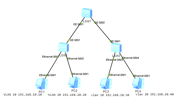
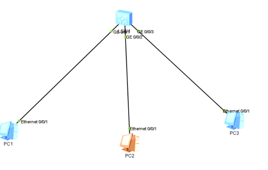
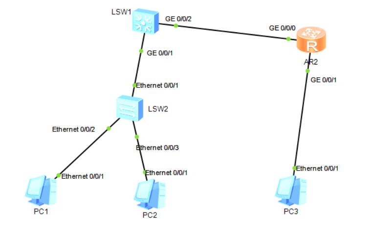
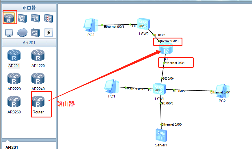
1. Experimental topology
2. Experimental requirements
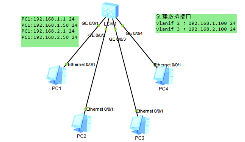
PC1 and PC3 belong to VLAN 10, PC2 and PC4 belong to VLAN 20, realizing mutual communication between different VLANs
3. Experimental process
1. Configure the Layer 3 switch SW1
SW1:
sys
sys sw1
vlan b 10 20
int vlan 10
ip add 192.168.10.1 24
int vlan 20
ip add 192.168.20.1 24
int g 0/0/1
port link-type trunk
port trunk allow-pass vlan 10 20
int g 0/0/2
port link-type trunk
port trunk allow-pass vlan 10 20
q
2. Configure the Layer 2 switch SW2
SW2:
sys
sys sw2
vlan b 10 20
int g 0/0/1
port link-type trunk
port trunk allow-pass vlan 10 20
int e 0/0/1
port link-type access
port default vlan 10
int e 0/0/2
port link-type access
port default vlan 20
qu
3. Configure the Layer 2 switch sw3
sw3:
sys
sys sw3
vlan batch 10 20
int g 0/0/1
port link-type trunk
port trunk allow-pass vlan 10 20
int e 0/0/3
port link-type access
port default vlan 10
int e 0/0/4
port link-type access
port default vlan 20
q
4. Configure PC
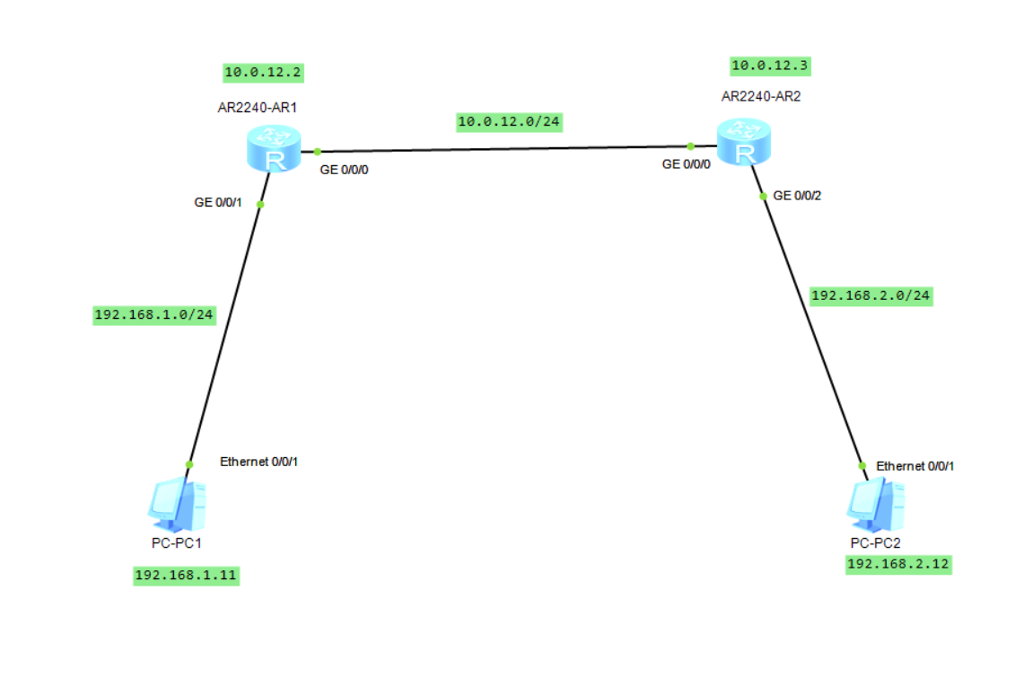
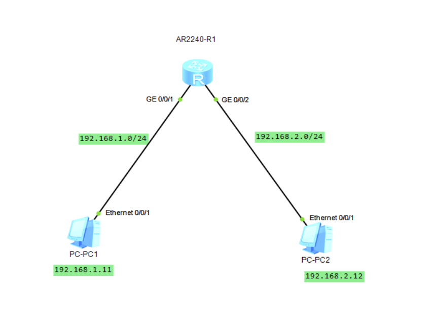
PC1:
IP address: 192.168.10.10
Mask: 255.255.255.0
Gateway: 192.168.10.1
PC2:
IP:192.168.20.20
Mask: 255.255.255.0
Gateway: 192.168.20.1
PC3:
IP:192.168.10.30
Mask: 255.255.255.0
Gateway: 192.168.10.1
PC4:
IP:192.168.20.40
Mask: 255.255.255.0
Gateway: 192.168.20.1
Four, test
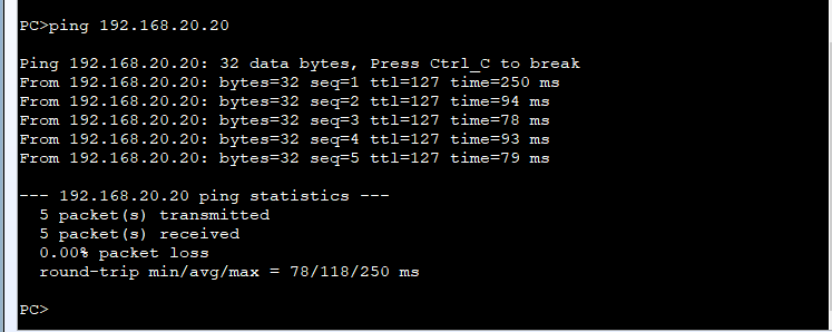
PC1 ping PC2
PC2 ping PC3
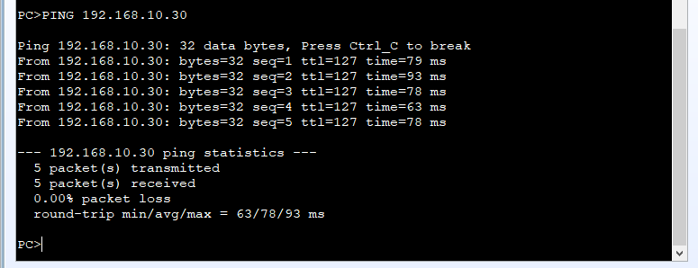
Communication can be achieved between different VLANs. The experiment was successful.
Attach:
Inter-VLAN communication can also be achieved through sub-interfaces under the router interface and through single-arm routing. Interested parties can find information by themselves.
Intelligent Recommendation
Huawei Ensp Simulator Experiment: Layer 3 Switches Inter-VLAN Communication
The three-layer switch vlan communicates with each other, and the topology diagram is as follows Set up the topology diagram of the experimental environment and start the experiment. I won’t giv...
How to use Huawei Layer 3 switches to realize the communication between different VLANs
1. Topology Layer 3 switches have routing functions, and Huawei switches are no exception. Use vlanif to create a gateway, set each interface type to access port, create different VLANs, and bind VLAN...

The most comprehensive VLAN technology for small and medium-sized networks (3)-Realizing communication between different network segments-the principle of Layer 3 switching (routing)...
Realize communication between different network segments Experiment overview: As shown in the above two figures, the communication between multiple VLANs is established on the basis of Layer 3 switchi...

[Job] Connect 2 switches to 2 PCs respectively, set different vlans to realize intercommunication between different vlans
Connect 2 switches to 2 PCs respectively, set different vlans to realize intercommunication between different vlans After configuration, set the PC to 192.168.1.1 192.168.1.2 192.168.1.3 192.168.1.4 C...
Huawei ensp-vlan routing-Layer 3 switching (2)
There is also a three-layer exchange method, in my homepage-three-layer exchange (1) Configure Layer 3 switching This time introduces another configuration method for configuring Layer 3 switching to ...
More Recommendation
eNSP: Realize communication between hosts on different network segments (static routing)
Continuing from the previous blog, this article we will analyze when two hosts and routers are not directly connected, that is, when there are multiple routers between the two hosts, how should we con...
eNSP: Realize communication between hosts on different network segments (direct routing)
Direct routing, as the name implies, means that two hosts are directly connected to the router. We want to realize the communication between PC1 and PC2, the specific configuration steps are as follow...
Huawei eNSP-2 different network segments-build a server
Configuration Requirements to be configured R1 router configuration Host configuration DNS configuration Success sign...

Configure Layer 3 switches to realize network connectivity (SVI) in different areas, two switches are connected to one Layer 3 switch
The experimental results are as follows: Experimental software: Cisco Packet Tracer Experimental tools: 4 PCs, 2 Layer 2 switches (switches 2950-24), 3 Layer 3 switches (3560-24PS), 4 Copper Straight-...
Huawei ensp-vlan routing-Layer 3 switching
Foreword: The traditional switch of VLAN cannot realize the two-layer message forwarding between different VLANs, so routing technology must be introduced to realize the communication between differen...