【Quartus II】 D trigger
tags: FPGA FPGA development
Articles directory
D trigger
D trigger is a memory function with memory function, two stable state information storage devices, which constitute a variety ofSequential circuitThe most basic logic unit is also an important unit circuit in digital logic circuits.
Therefore, D trigger has a wide range of applications in digital systems and computers. The trigger has two stable states, namely "0" and "1". Under a certain external signal, it can be flipped from one stable state to another stable state.
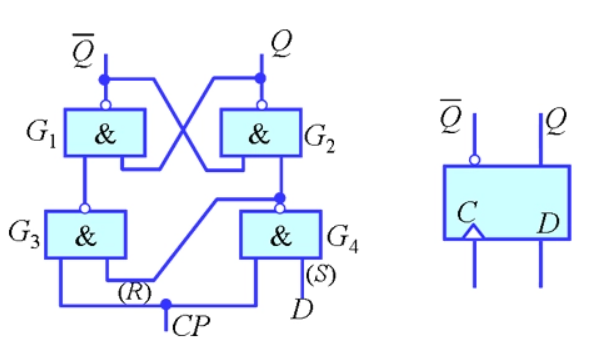
D trigger is integratedtriggerThe trigger composed of the door circuit. There are two types of triggers two types: level trigger and edge triggering. The former can be triggered when CP (clock pulse) = 1, and the latter is mostly triggered at the front of the CP (positive jump 0 → 1).
The second state of D trigger depends on the state of the front d side, that is, the secondary state = D. Therefore, it has two functions: setting 0 and 1.
For edge D triggers, because the circuit has maintained blocking effect during the CP = 1 period, during the CP = 1 period, the data state of the D -end changes will not affect the output state of the trigger.
D trigger is widely used, available for useDigital signalStocking, displacementRegister, Frequency and waveform generator.
1. Division circuit design D trigger to perform simulation verification
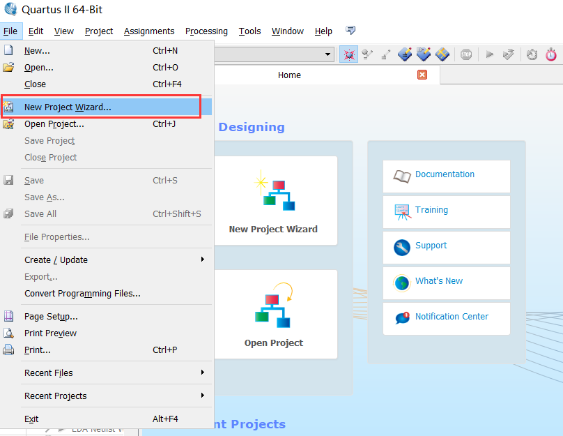
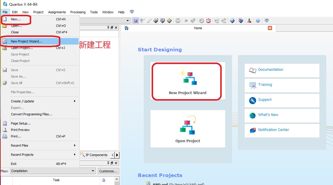
1. New project
Click FILE-> New Project Wizard ...

Specify the preservation path and file name
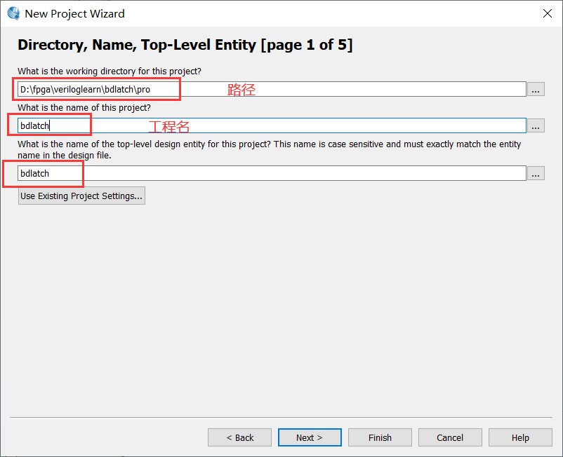
Use AC620 development board here

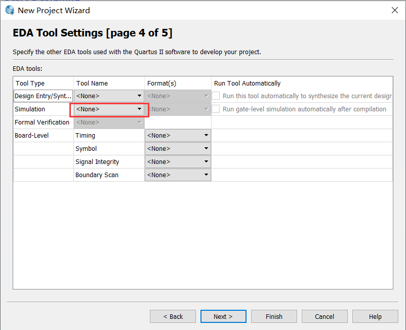
EDA tools-simulation selects NONE and uses waveform file simulation
Click Finish to complete the creation.
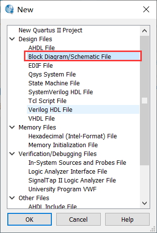
2. Create a schematic file
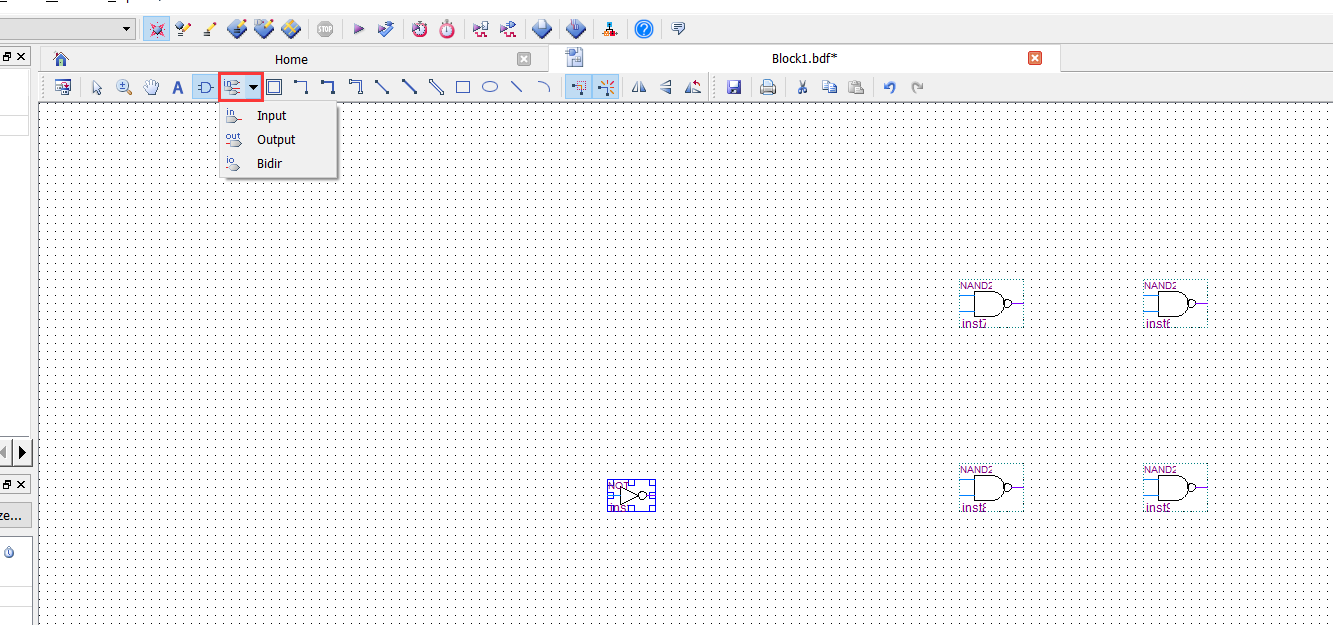
Click FILE-> New-> Block Diagram/Schematic File
Enter NAND2, the corresponding two inputs and non -door on the right will appear, add 4 with the door NAND2 and 1 non -door NOT in turn
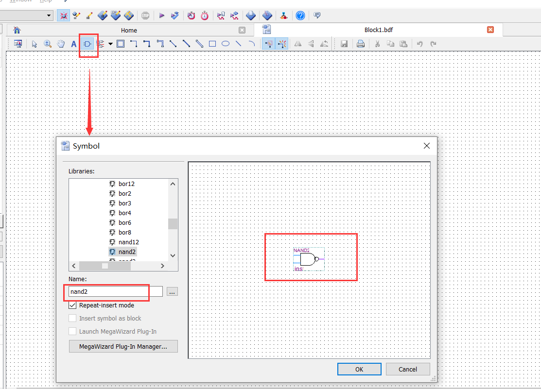
The input and output tools of the toolbar, and the connection tool design as shown below
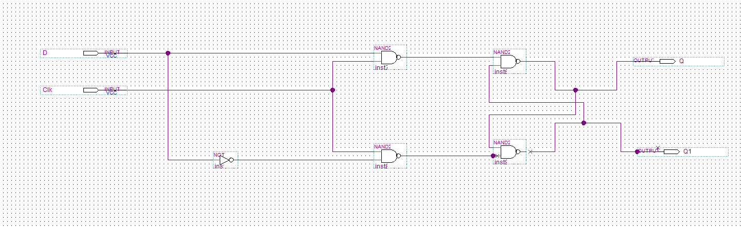
Save circuit diagram
Start analysis and synthesis, compile the schematic diagram file. If there is an error, the schematic diagram needs to be modified.
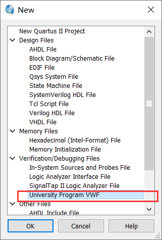
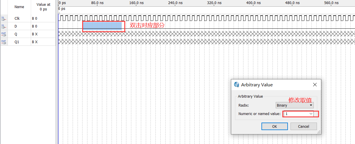
3. Create VWM format waveform file
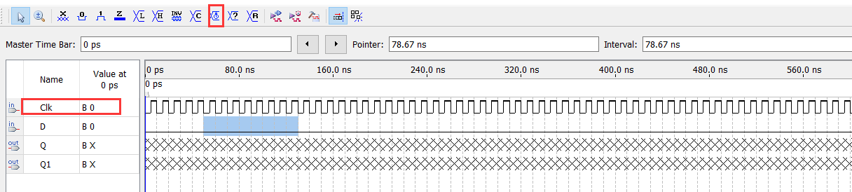
Choose CLK to modify the waveform
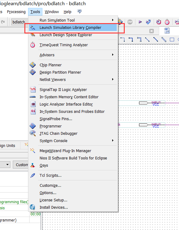
Compile
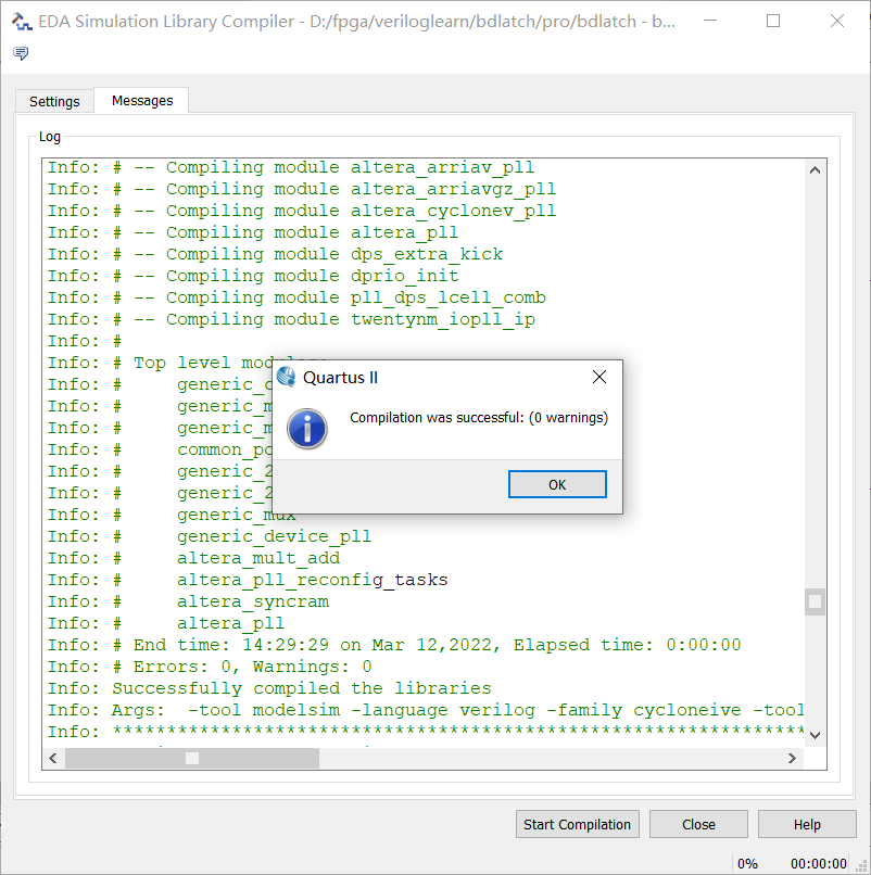
Select the simulation device to compile
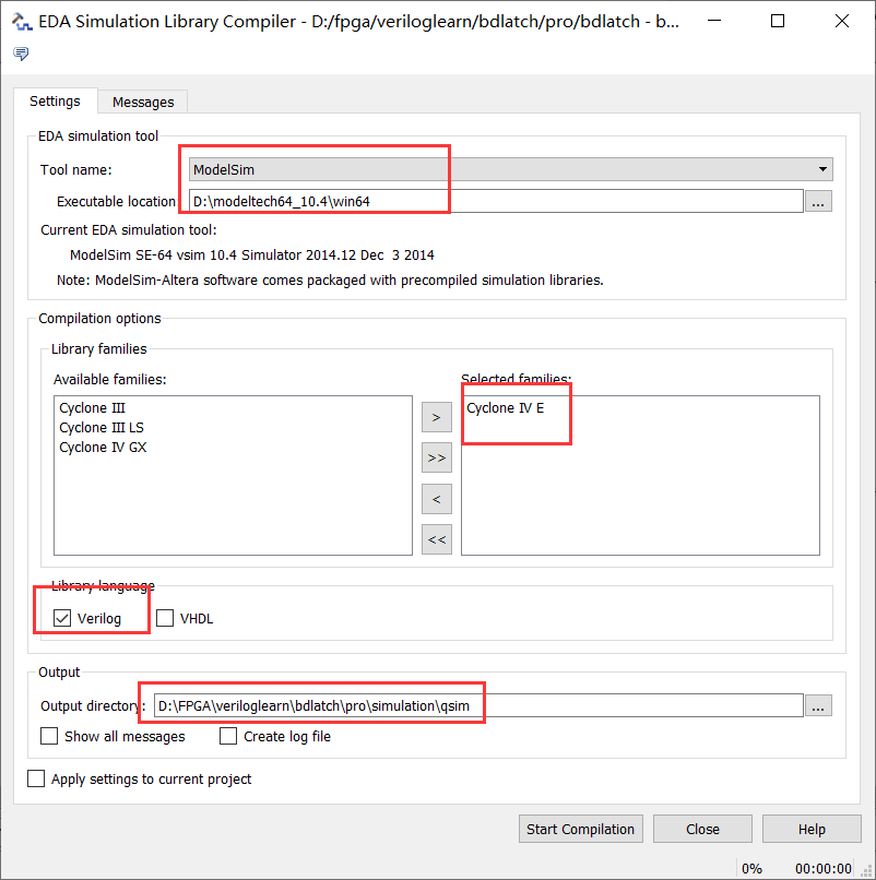
Click Start Compilation
No warning
Waveform simulation
Seeing waveform changes is delayed.
2. Call D trigger and perform simulation verification
1. New project
Above
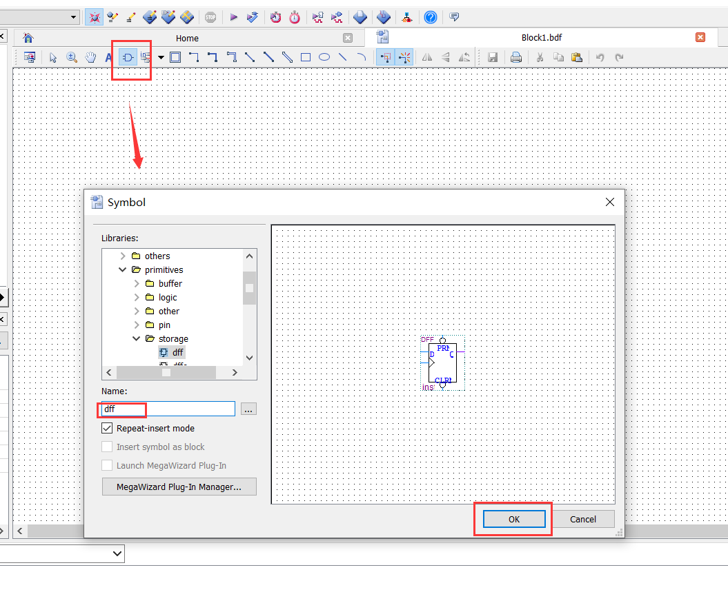
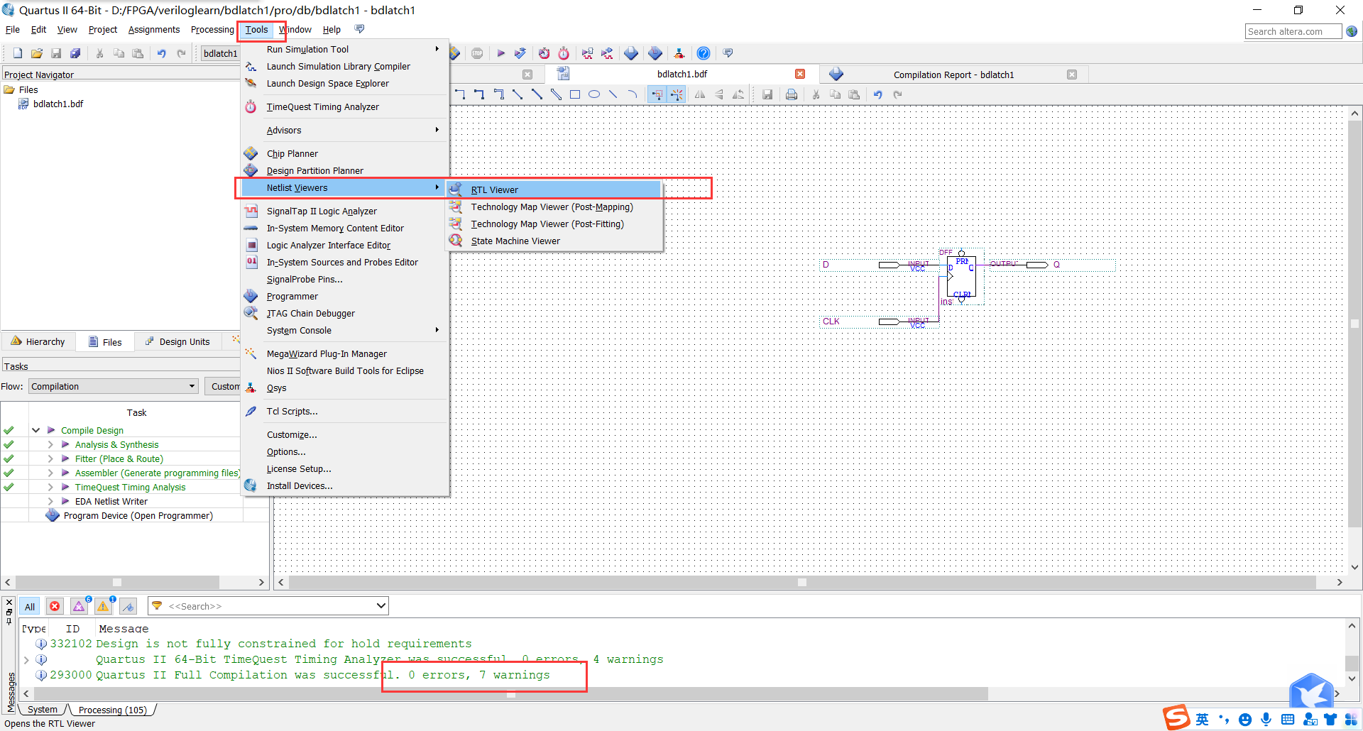
2. Create box file
Call D trigger
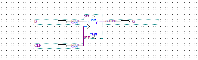
Draw effect
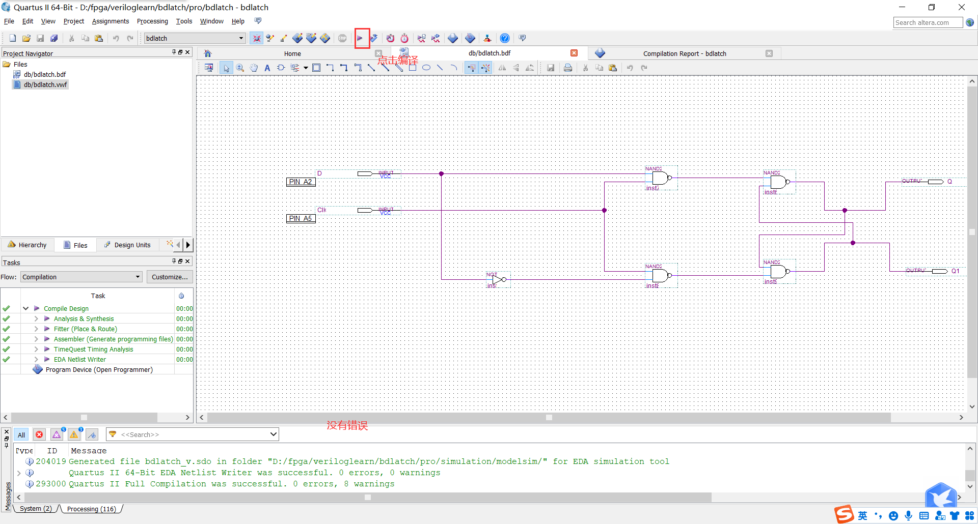
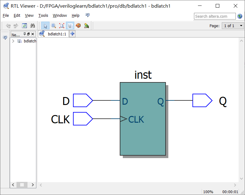
3. Compile the schematic file, view the hardware circuit diagram
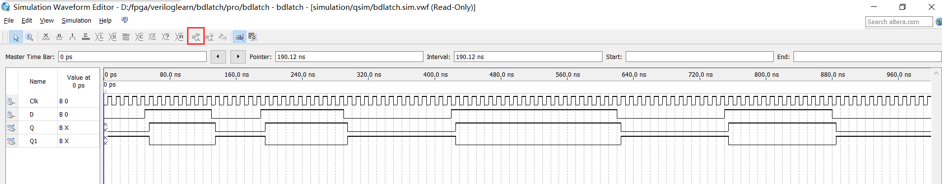
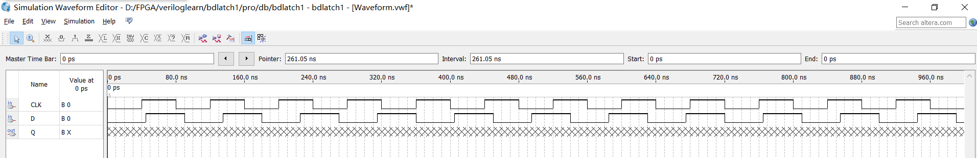
4. Create VWM format waveform file Timely simulation
Edit wave shape
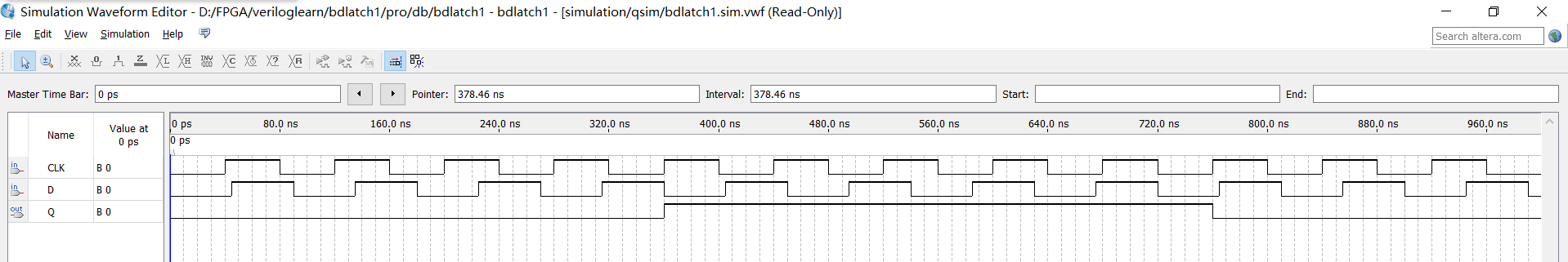
Simulation results
3. Writing a D trigger inVerilog language to perform simulation verification
1. New project
Above
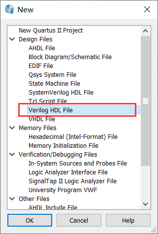
2. Create a new Verilog file
Write content
// dwave is the file name
module bdlatch2(d,clk,q);
    input d;
    input clk;
    output q;

    reg q;

         always @ (posedge clk) // We use the right clock to make its sensitive signal
    begin
                 Q <= d; // When the rising edge is valid, capture D to Q
    end
endmodule
Save as BDLATCH2.V and compile
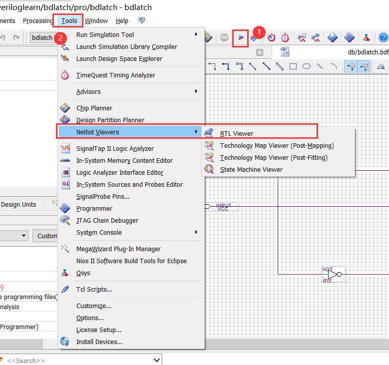
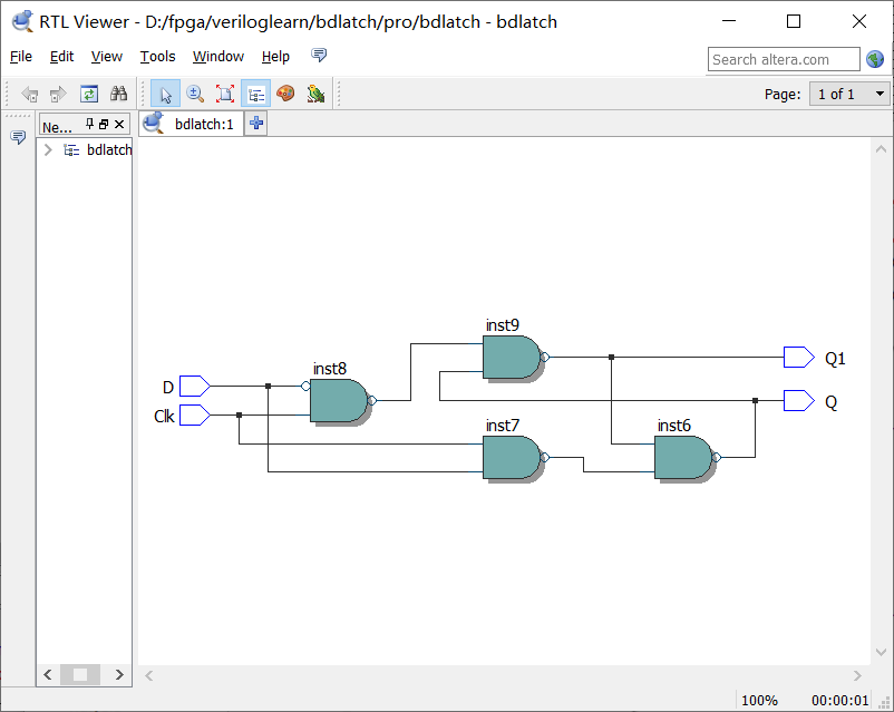
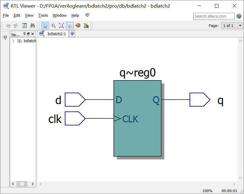
3. View generated circuit diagram
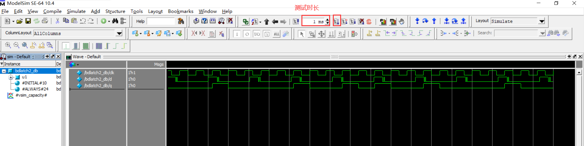
4. Use Verilog language to write code for simulation test
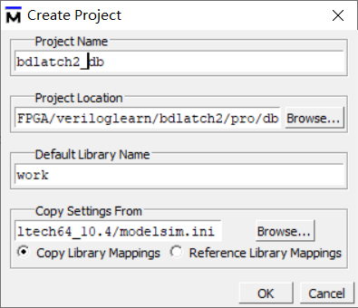
① Open Modelsim's new project
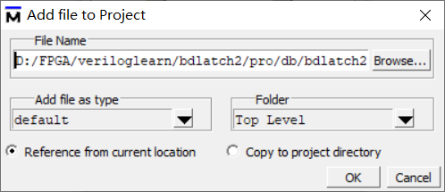
② Select to add existing files
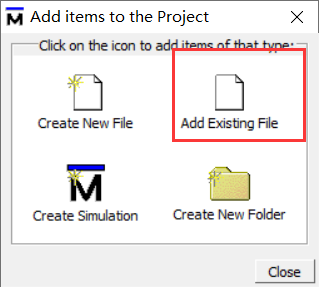
Add the above .v files above
③ Create a new file
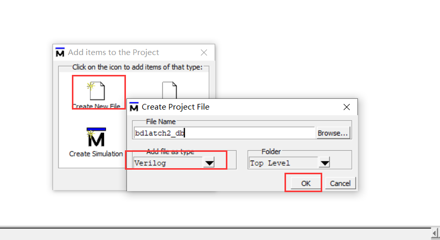
Close ADD items to the project
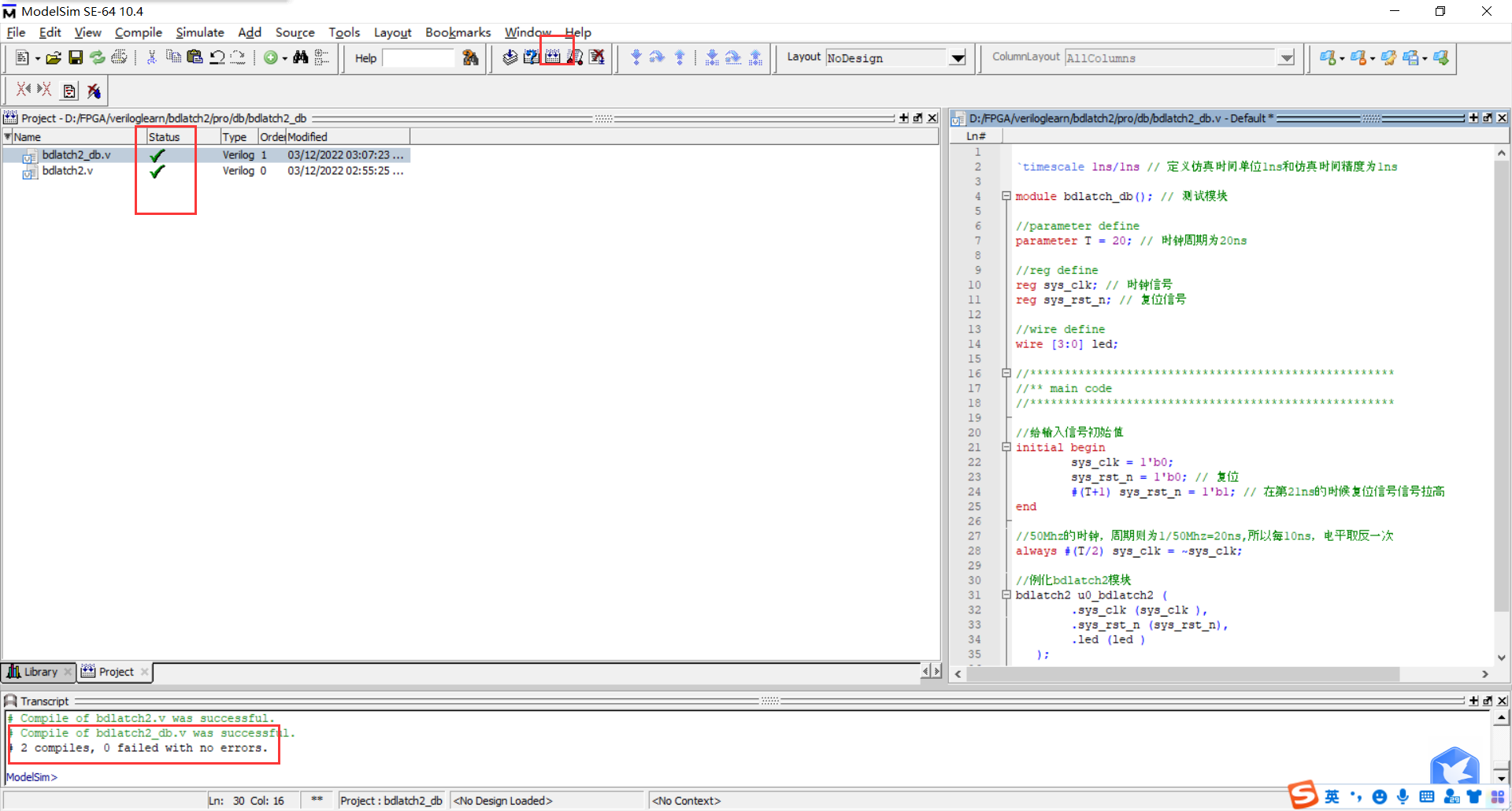
Double -click BDLATCH2_DB.V file
Add code
Compile
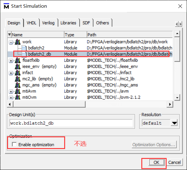
④ Configuration simulation environment
Click Simulating-> Start Simulation ...
Right -click BDLATCH2_DB to select ADD WAVE
4. Summary
The D trigger simulation results implemented by the above three methods can be found that when the D trigger is a high level, when the CLK is at the rising edge, the output Q signal will change.
5. Reference link
Intelligent Recommendation
[FPGA] Quartus-II Getting Started Implementation D Director
Table of contents 1. Design D trigger based on door circuits 1. Create engineering 2. Design door circuit 3. Compile simulation 2. Call the D trigger circuit in Quartus-II 3. Realize D trigger based o...
quartus simulation 21: JK trigger and D trigger realize 110 sequence detector
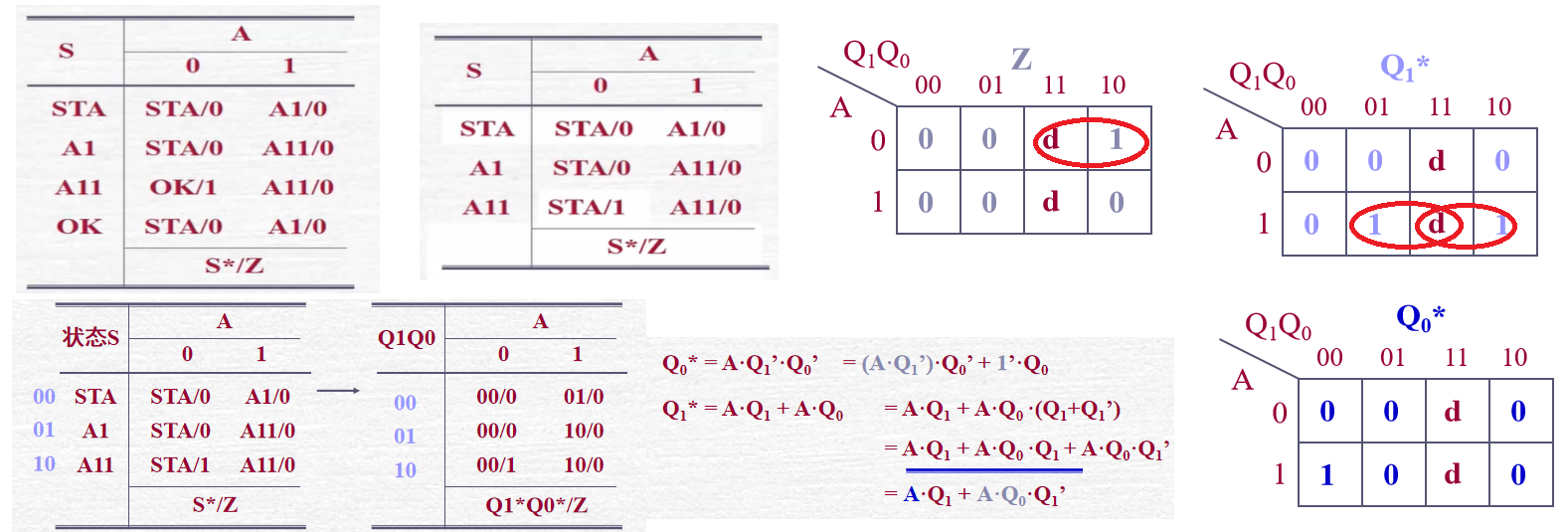
List the state transition diagram, define four states according to the language description, Received nothing Received 1 Received 11 Received 110 According to the equivalent principle of producing the...
QUARTUS-LL uses three ways to implement D trigger function simulation and timing waveform simulation detailed steps
table of Contents I. Introduction to D Trigator Second, create a D trigger schematic and simulation 2.1 New Project 2.2 Creating a Schematic File 2.3 Compilation Schematic File 2.4 Creating a VWF file...

Quartus ii incremental compilation
First of all, we must first look at the Quartus II compilation process is a matter of how to understand this process is very simple, look at the following picture, no one is strange: After we have ful...

Quartus II using Testbench
A recent experiment to use Testbench, had wanted to do a do online tutorials shining, the results of the pit too, so I decided to write one. I use Quartus II 16.0, if a different version does not matt...
More Recommendation
and connecting quartus ii modelsim
1. Tap tool-> options-> EDA Tool Options, fill in the installation path modelsim modelsim bar and modelsim-altera 2. Click assignment-> settings-> simulation, select the column name in the...
Quartus II simulation
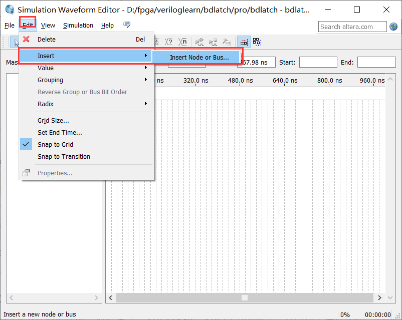
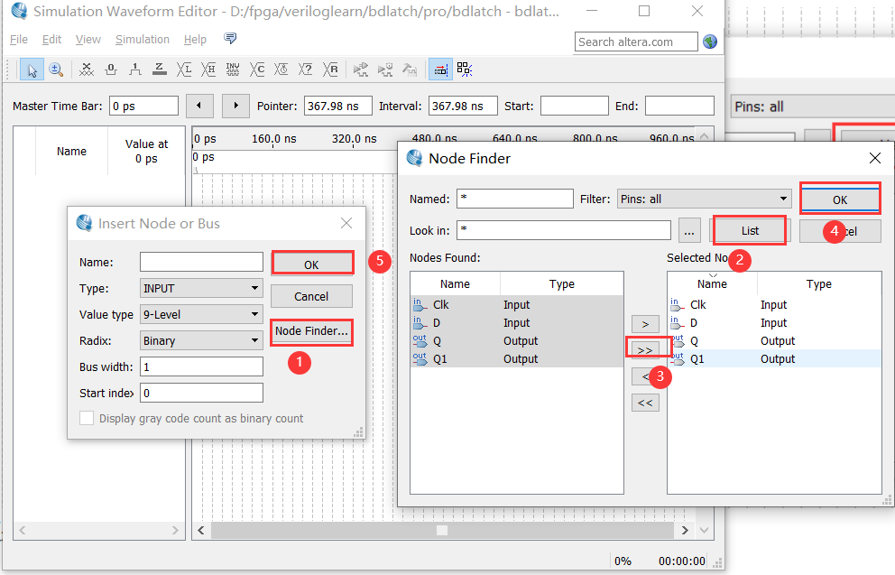
Quartus II simulation using university program VWF 1.File-> new-> university program VWF-> OK to open the simulation page 2.edit-> insert-> insert node or bus or double-click an empty s...
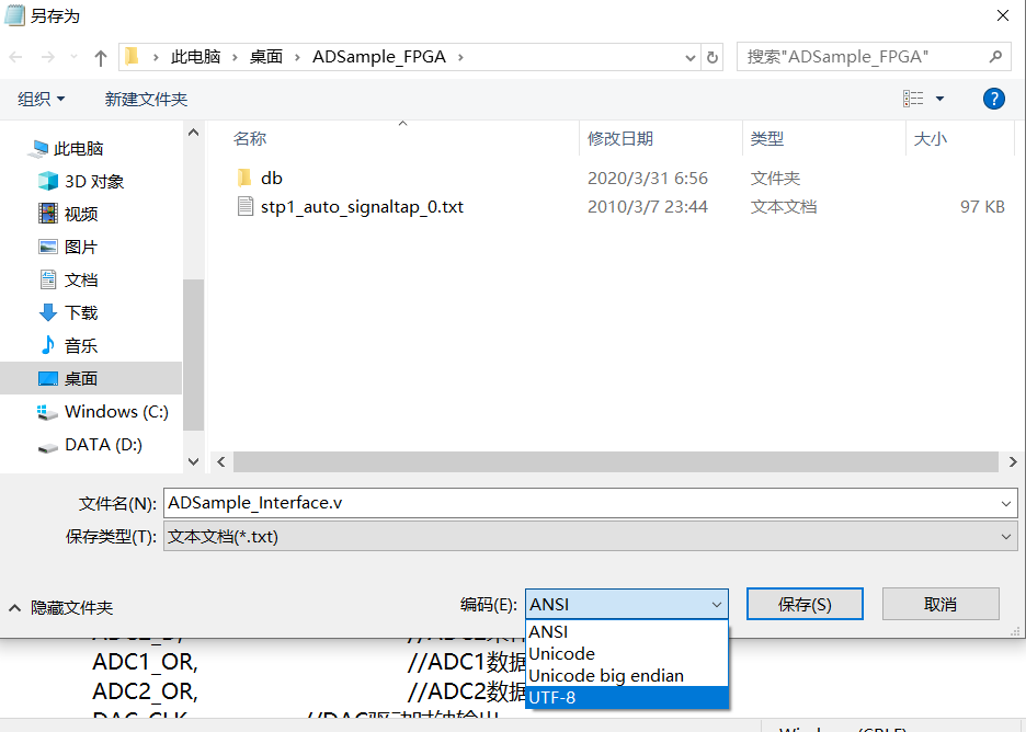
quartus ii Chinese garbled
The reason for this distortion is that in Quartus ii upgrade, replace the coding standards. quartus ii 11.0 The following version of the ANSI code, and the updated version 12.0 to 14.0, is the use of ...
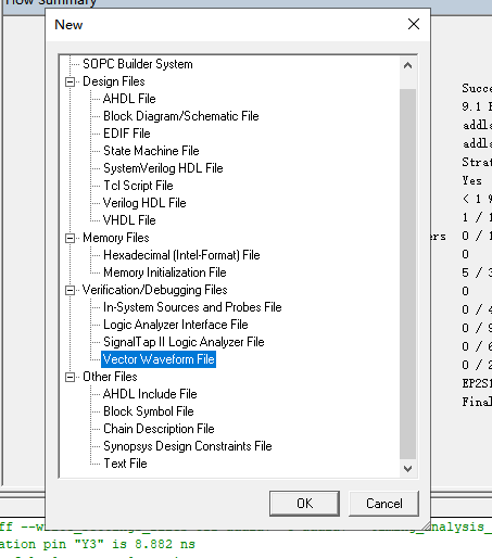
Quartus ii on waveform simulation
1. Click File, click new, Click on the blue part of the picture above, and then keep OK, the following interface appears Then execute the [File \ Save As…] menu command and save it as add1a.vwf...
Quartus II detailed use
This morning I did the first experiment of the "Principles of Computer Composition" class. Here is how to use Quartus II, hope to help those in need. 1. New construction project. 2. Fill in ...