MIPI DSI interface protocol introduction
tags: mipi dsi protocol
Since the MIPI DSI interface will be used recently, I have studied the MIPI Alliance Specification for DSI protocol document and summarized it
MIPI official website link:https://mipi.org/specifications/dsi-2 There are all DSI, CSI, D-PHY and other protocols
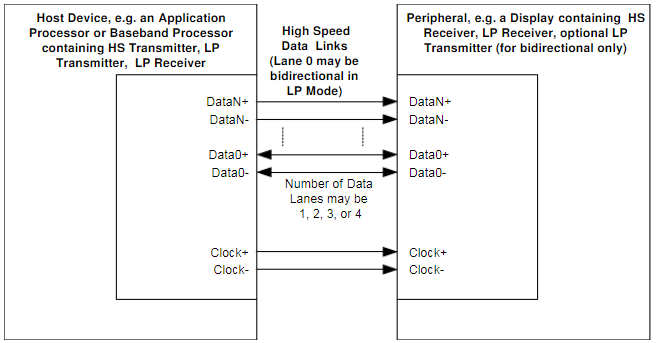
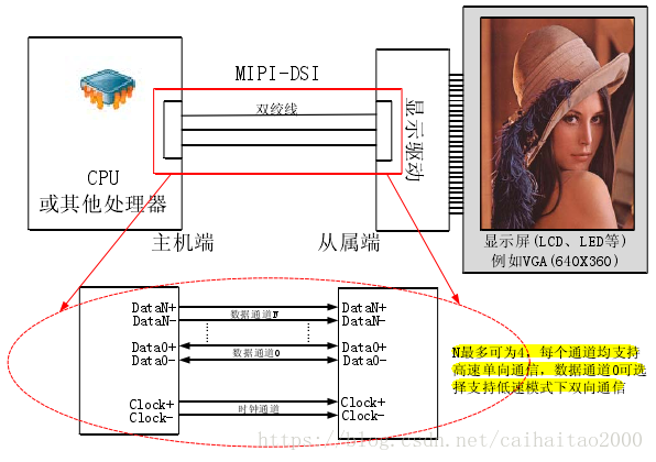
MIPI (Mobile Industry Processor Interface) is the abbreviation of Mobile Industry Processor Interface. MIPI (Mobile Industry Processor Interface) is an open standard for mobile application processors initiated by the MIPI Alliance. Commonly used are DSI (Display Interface) and CSI (Camera Interface). It is mainly used in the mobile phone industry. For example, the commonly used mobile phone processor is connected to the camera, and the display is connected to the mipi interface. The mipi interface transmits clocks and data in the form of differential pairs. Generally there are 1 pair of clock differential pairs, plus 1-4 pairs of data differential pairs. The connection method is shown below:
1 DSI Layer Definition
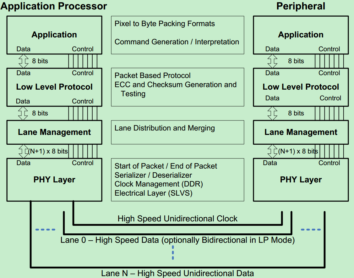
The following figure is the hierarchy definition diagram of DSI interface
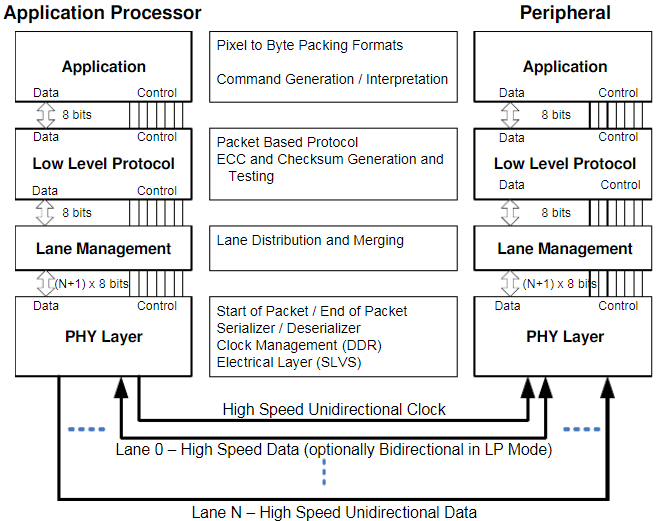
It can be seen from the picture that there are 4 levels
(1) PHY Layer: physical layer, used to specify the transmission medium, input and output circuits and capture data on the data line according to the clock.
(2) Lane Management: lane management, lane refers to a pair of differential pairs. Since the data line can have 1-4 lanes, the upper layer needs to be packaged with the data according to Sequentially sent to different lanes. The receiving end needs to receive data from different lanes in sequence and stitch them together in sequence. The "4 Multi-Lane Distribution and Merging" section will be described in detail later.
(3) Protocol Layer: In the low level protocol, when sending, the DSI protocol specifies the data packet method, defines the relevant content such as the header, and generates ECC, check code and other content to form a complete data packet. When receiving, the valid data inside is parsed according to the data packet format, and the content such as the packet header is removed.
(4) Application Layer: Application layer, which describes how to encode and decode the data in the data stream in a high-level protocol. Its format and content are mainly determined according to the type of display subsystem connected later. It can be composed of pixels in a specified format, or it can be a control command sent by a display controller.
2 Command and Video mode
Peripherals compatible with DSI interface support at least two basic operation modes: one of Command mode and Video mode. As for which mode is actually used depends on the structure and performance of the peripheral device.
Generally, peripheral devices are compatible with Command mode or Video mode. Some modules that support Video mode display also include a simple Command mode, so that you can refresh the screen with low-resolution images or Part of the screen is displayed, and operations such as closing the MIPI interface.
2.1 Command mode:
The main controller and peripheral display device exchange data mainly by sending commands and data to the display module of the peripheral device. The module contains a display controller, and the display controller contains local registers and frame memory , The system uses Command mode to read and write local registers and frame memory. In this way, the main controller indirectly controls the display of peripheral devices by sending commands, parameters and data to the display controller. At the same time, the main controller can also read the status information of the display module and the content of the frame memory. Therefore, in Command mode, a bidirectional data interface is required.
2.2 Video mode
The data transmission from the main controller to the peripheral devices is carried out in real-time pixel streaming. In the normal operation mode, the main controller must send the image data to the display module with sufficient bandwidth, otherwise there will be bad phenomena such as splash screen and flower screen. Video information can only be sent in high-speed mode.
In some device structures that support Video mode, some have a simple timing controller and some frame buffers. With these two modules, the display device can maintain part of the screen display or display low-resolution images during standby and in Low Power Mode. In this way, the MIPI interface can be closed to save energy consumption.
In order to reduce cost and interface complexity, when the system is only used in Video mode, the data interface may be made into a unidirectional interface.
2.3 Virtual Channel Capability
is used to enable one host controller to connect multiple physical display modules at the same time.
3 DSI Physical Layer DSI Physical Layer
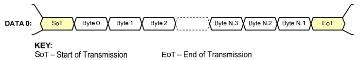
This part mainly introduces the packet format of the data sent by the DSI physical layer. The data exchange between the main controller and the peripheral devices is transmitted by one or more serial data signals and a follow-up clock . The method of sending high-speed serial data through the bus is called HS transmission or burst.
When the data lane does not send or receive data, the interface enters the Low Power State (LPS) state. The following figure is the basic data structure of HS transmission, N represents the total number of bytes of data sent. At the beginning of each frame, there is a SoT to start transmission, followed by N bytes of data, after the data is sent, then send EoT to end the transmission
3.1 Data lane direction
The physical link layer of DSI is composed of 1-4 data lanes and a clock lane. In the Command mode system, the data lane0 is bidirectional, and the other data lanes are unidirectional In the video mode system, the data lane0 can be either bidirectional or unidirectional, and the other data lanes are unidirectional. Regardless of the command mode or the video mode, the clock lane is driven by the main controller and cannot be driven by peripheral devices.
Forward (from the main controller to the peripheral device) Low Power data transmission only uses lane0, and reverse transmission on data lane0 can only be in Low Power mode. Peripheral equipment must be able to receive data under Low Power and high speed
3.2 Command Mode Interfaces
The main controller is in Command Mode, and the minimum physical layer requirements are:
Data lane module:CIL-MFAA(HS-TX,LP-TX,LP-RX,and LP-CD)
Clock lane moduel:CIL-MCNN(HS-TX,LP-TX)
The peripheral main controller is in Command Mode, and the minimum physical layer requirements are:
Data lane module:CIL-SFAA(HS-RX,LP-RX,LP-TX,and LP-CD)
Clock lane moduel:CIL-SCNN(HS-RX,LP-RX)
3.3 Video Mode Interfaces
The main controller is in Video Mode, the physical layer minimum requirements are:
Data lane module:CIL-MFAN(HS-TX,LP-TX)
Clock lane moduel:CIL-MCNN(HS-TX,LP-TX)
The peripheral main controller is in Video Mode, the physical layer minimum requirements are:
Data lane module:CIL-SFAN(HS-RX,LP-RX)
Clock lane moduel:CIL-SCNN(HS-RX,LP-RX)
3.4 Clock management
The DSI clock is generated by the main controller and sent to the peripheral devices. In some systems, it can have multiple uses:
(1) DSI Bit Clock: On the data receiving side, PHY Layer uses this clock as the source synchronous clock to capture serial data. When transmitting data, the clock is valid.
(2) Byte Clock: Byte clock, which is divided by DSI Bit Clock and used as byte clock when data exchange between protocol layer and application layer. In HS transmission, each byte of data is accompanied by a byte clock.
(2) Application Clock: Application layer clock, also obtained by DSI Bit Clock frequency division, can be used as a clock for some modules of peripheral devices.
4 Multi-Lane Distribution and Merging N data lanes, data distribution and merge
In order to transmit different bandwidth data, the data lane has 1-4lane, so when there are multiple data lanes, it involves how to distribute the data packaged in the upper low level protocol to more The lanes are transmitted, and Lane Management in the DSI hierarchy does the job of distributing this data to different lanes. At the sending end, the operation of data distribution to each lane through this module is shown in the figure below.

At the receiving end, this layer receives data from each lane and assembles it into a complete data packet and sends it to the previous level

The lane distributor takes N bytes from the HS transmission of any byte length sent from the upper layer and fills them into N lane transmission modules, and sends the N words in parallel through N lanes Section. Before sending data, all lanes need to send a SoT signal to their corresponding receiving units in parallel at the same time, indicating that the first byte of the data packet starts to be sent. After sending the SoT, lanes start to send N in parallel A data group of bytes, for example, in a 2 lane system, Byte0 of the data packet is sent in lane0, Byte1 is sent in lane1, Byte2 is sent in lane0, and Byte is sent in lane1. Send in this order.
4.1 Sot and EoT in Multi-Lanes
Because the length of HS transmission is any number of bytes, it is possible that the length is not an integer multiple of the number of lanes, and some lanes will finish sending data before other lanes, so In the Lane Management Layer, it will fill the data to an integer multiple of the length of the lane, and at the same time pull the "valid data" signal of the lane that sent it low, indicating that the data sent at this time is invalid. (For example, the length of HS transmission is 178 bytes, and the number of lanes is 3, so that the Lane Management Layer will be filled with 2 bytes of data, so that the length is an integer multiple of the number of lanes)
Although all lanes send data in parallel after sending SoT at the same time, since each lane sends data independently, it is possible that some lanes will finish sending data before other lanes and send EoT one cycle earlier. The following figure shows the way in which each lane sends data at different HS transmission lengths and 3 lanes

5 DSI Protocol Layer
At the sending end of the DSI interface, the parallel image data is converted into the form of data packets in the Protocol Layer. At the same time, the packet agreement information and packet header will be added. Then send it to the PHY Layer through the Lane Management Layer. Then the PHY Layer serializes the data and sends it to the peripheral device through the lane. Peripheral equipment samples the data in the opposite way to the sender.
If multiple lanes are used to transmit data, Lane Management Layer will distribute the data packets to multiple PHY Layers, one PHY Layer corresponds to one data lane. The protocol and format of the image data packaging have nothing to do with the use of several lane transmissions. Lane is just a physical transmission medium.
5.1 Multiple Packets per Transmission
The simplest transmission mode is that a Transmission contains only one data packet, but when there are multiple data packets to be sent, it is still a Transmission to send a packet, so when sending, in LPS and HS Frequent mode switching will severely limit the transmission bandwidth. DSI Protocol allows multiple data packets to be connected and sent in a Transmission, which will significantly increase the limited bandwidth.
The PHY Layer has two data transmission modes, HS and LP. Before a HS Transmission starts, the PHY Layer first sends a SoT sequence to the receiving end. After that, the data or command packet can be in HS mode Next transmission. There may be multiple data packets in a Transmission transmission. At this time, at the end of transmission, the PHY Layer sends a dedicated EoT end signal to indicate the end of transmission.
In order to enhance the robustness of the entire system, DSI defines a dedicated EoT package (EoTp) in the Protocol Layer to indicate the end of a Transmission. In order to be compatible with the early DSI system, the function of generating and interpreting EoTp can be enabled and disabled. The following figure is the case where EoTp is not enabled. The upper half is the case where 3 data packets are sent separately, and the lower half is the case where 3 data packets are sent in one Transmission.

The following figure is the case where EoTp is enabled, the upper part is the case where 3 data packets are sent separately, and the lower part is the case where 3 data packets are sent in one Transmission. The red circle is the EoTp package.

5.2 Packet Composition
Packets are divided into two types: short packets and long packets
Short data packet: 4 bytes in length, mainly used for transmitting commands, reading and writing registers, the structure is shown in the following figure.
DI: data identifier, 1 byte, [B7:B6] means virtual channel (0-3), because a main controller can connect multiple peripheral devices (up to 4 ), so use virtual channels to represent different external peripheral devices.
[B5:B0] indicates the data type. Used to indicate whether it is a long packet or a short packet, and the packet format, as shown in the following figure,

Data0, Data1: 2 bytes, indicating the data to be transmitted
ECC: 1 byte, error correction code

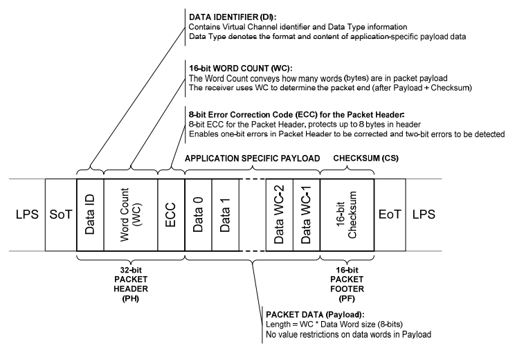
Long data packet: The payload length is 0-65535 bytes, which is mainly used to transmit a large amount of image data or some control commands. The structure is shown in the following figure.
DI: data identifier, 1 byte, [7:6] indicates the data lane number (0-3) corresponding to the virtual channel, and [5:0] indicates the data type.
WC:word count, 2 bytes, the payload length in the packet, because the bit width is 16 bits, so the maximum length can be expressed as 65535 bytes, the receiver is through the data The length is counted to determine whether a packet has been received.
ECC: 1 byte, error correction code
Data0,1…..: payload
CHECKSUM: 2 bytes, check code
So the frame length is 4+(0-65535)+2=6-65541 bytes
The following is the meaning of the 6-bit wide data type, which is used to indicate the data type or command transmitted by the packet, such as data type=0x01. Field sync signal start flag.

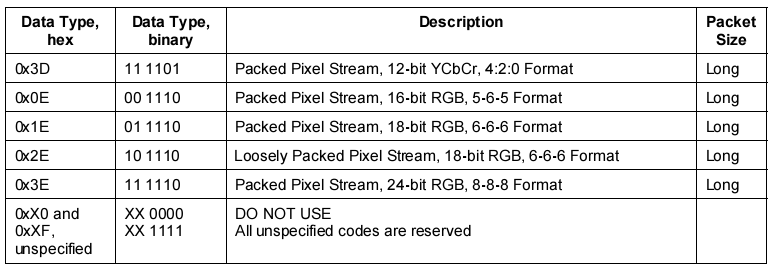
The following is a long data packet format with data type=0x0E. 0x0E indicates that the payload of the packet is a 16-bit RGB (5-6-5) format pixel stream. The specific meaning of other data types can be viewed in the MIPI DSI protocol.

5.3 Transmission Packet Sequence
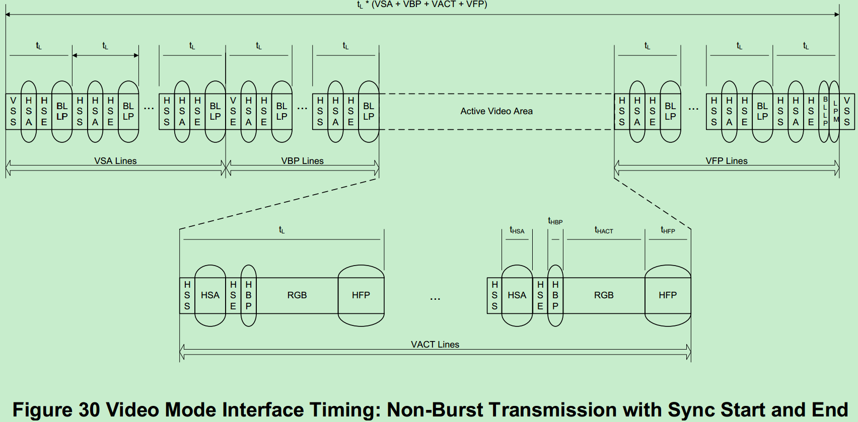
When transmitting data in video mode, DSI supports the following three types of packet formats or packet sequential transmission:
(1) Non-Burst Mode with Sync Pulses: enables peripheral devices to regain the original image timing, including the sync pulse width.
(2) Non-Burst Mode with Sync Events: Similar to the above, here only replaces Sync Pulses with Sync Events.
(3) Burst Mode: Through time compression, RGB pixel packets can be transmitted in a shorter time, which allows more time for transmission of other data.
to sum up:
The MIPI transmission mode is mainly distinguished according to its D-PHY physical layer, which is divided into:
Low power mode (Lower Power), in this mode, forward transmission data can only use lane0, reverse transmission can also only use lane0, transmission rate 10Mhz
High speed mode (high speed), transmission rate 80M-1Gbps/lane
D-PHY operating modes:
escape mode ,high speed mode ,control mode.
Command mode: In this operation mode, it can be either High speed or LP transmission mode. The data lane0 is bidirectional, and the other data lanes are unidirectional
Video mode: In this operation mode, High speed transmission mode must be used. The data lane0 can be either bidirectional or unidirectional, and other data lanes are unidirectional
Intelligent Recommendation
Display (4) - MIPI-DSI Interface
MIPI-DSI three video-mode understanding MIPI_DSI_MODE_VIDEO_BURST, indicating Video Burst Mode. MIPI_DSI_MODE_LPM represents the default to send an initialization sequence in LP mode. MIPI_DSI_MODE_EO...
MIPI literacy - DSI introduction (2)
This article briefly introduces three operating modes of Mipi DSI Video Mode: Non-Busrt Mode with Sync Pluses Non-Burst Mode with Sync Events Burst Mode Where Non-Busrt Mode With Sync Pluses mode can ...
MIPI literacy - DSI introduction (1)
Directory address:http://blog.chinaaet.com/justlxy/p/5100052503 In order to facilitate understanding of the following content, first introduce the abbreviations defined in several DSI protocol d...

[Note Sharing] [Display] DSI of MIPI Protocol
Introduction DSI stands for Display Serial Interface, which is mainly used for an interface of the display module. It is generated based on the MIPI protocol. There are also CSI (camera serial interfa...

LCD mipi DSI interface driver debugging process
origin: March 31, 2017 22:15:14liwei16611 Reading number: 17741 Tags:android lcd Framemipi DSI More Personal classification:Android LCD development Copyright statement: This article is an origi...
More Recommendation

MIPI DSI
This article is reproduced from: Overview: MIPI contains many communication protocols. This chapter only talks about dsi (display serial interface) used by mipi for display interface. MI...
MIPI-DSI, MIPI-CSI, LVDS and other interface analysis
MIPI The MIPI Alliance, or Mobile Industry Processor Interface (MIPI) Alliance, is an open standard and a specification developed by the MIPI Alliance for mobile application processors. Mainly the sta...

LCD interface series - MIPI DSI clock calculation and common concept distinguishing
Article catalog Overview Clock calculation LCD basic clock concept DSI clock calculation DSI's "Mode" concept distinguishes LCD screen mode Command mode and VIDEO mode Three modes of the vid...
One sheet to understand the SPMI interface introduction in the MIPI protocol
MIPI Alliance Specifications Many interface protocols, look at SPMI today, understand the people of the PMIC power management chip know, now many main chips and PMICs use this interface to communicate...

Mipi dsi screen debugging
In the past two days, a new project was screened, and an adapter cable was added to the old machine to debug in advance. I haven't adjusted the screen for a long time. I used to remember a 1,2. There ...