Example Modelica - exemplary digital to analog converter circuit
Digital to analog converter (D \ A conversion) is an important interface processing, the digital signal into an analog signal which will drive the external device.
In this example D \ A converter using the ratio method of the adder. Input resistor value of the adder represents the binary input code heavy weight.
Circuit

curve

V=-(0*(1000/1000)+1*(1000/2000)+0*(1000/4000)+1*(1000/8000))
= -(1/2+1/8)
= -0.625
program
model cb
Modelica.Electrical.Analog.Basic.Ground ground1 annotation(
Placement(visible = true, transformation(origin = {-92, 2}, extent = {{-10, -10}, {10, 10}}, rotation = 0)));
Modelica.Electrical.Analog.Ideal.IdealizedOpAmpLimted idealizedOpAmpLimted2 annotation(
Placement(visible = true, transformation(origin = {16, -40}, extent = {{-10, -10}, {10, 10}}, rotation = 0)));
Modelica.Electrical.Analog.Basic.Ground ground5 annotation(
Placement(visible = true, transformation(origin = {58, -74}, extent = {{-10, -10}, {10, 10}}, rotation = 0)));
Modelica.Electrical.Analog.Sources.ConstantVoltage constantVoltage5(V = -15) annotation(
Placement(visible = true, transformation(origin = {26, -64}, extent = {{-10, -10}, {10, 10}}, rotation = 0)));
Modelica.Electrical.Analog.Basic.Ground ground6 annotation(
Placement(visible = true, transformation(origin = {-48, -56}, extent = {{-10, -10}, {10, 10}}, rotation = 0)));
Modelica.Electrical.Analog.Basic.Resistor resistor1(R = 1000) annotation(
Placement(visible = true, transformation(origin = {30, 22}, extent = {{-10, -10}, {10, 10}}, rotation = 180)));
Modelica.Electrical.Analog.Sources.ConstantVoltage constantVoltage1(V = 15) annotation(
Placement(visible = true, transformation(origin = {26, -10}, extent = {{-10, -10}, {10, 10}}, rotation = 0)));
Modelica.Electrical.Analog.Basic.Ground ground2 annotation(
Placement(visible = true, transformation(origin = {60, -20}, extent = {{-10, -10}, {10, 10}}, rotation = 0)));
Modelica.Electrical.Analog.Interfaces.Pin pin annotation(
Placement(visible = true, transformation(origin = {99, -41}, extent = {{-3, -3}, {3, 3}}, rotation = 0), iconTransformation(origin = {99, -41}, extent = {{-3, -3}, {3, 3}}, rotation = 0)));
Modelica.Electrical.Analog.Basic.Resistor resistor2(R = 8000) annotation(
Placement(visible = true, transformation(origin = {-34, 26}, extent = {{-10, -10}, {10, 10}}, rotation = 180)));
Modelica.Electrical.Analog.Basic.Resistor resistor3(R = 4000) annotation(
Placement(visible = true, transformation(origin = {-34, 10}, extent = {{-10, -10}, {10, 10}}, rotation = 180)));
Modelica.Electrical.Analog.Basic.Resistor resistor4(R = 2000) annotation(
Placement(visible = true, transformation(origin = {-34, -6}, extent = {{-10, -10}, {10, 10}}, rotation = 180)));
Modelica.Electrical.Analog.Basic.Resistor resistor5(R = 1000) annotation(
Placement(visible = true, transformation(origin = {-34, -22}, extent = {{-10, -10}, {10, 10}}, rotation = 180)));
Modelica.Electrical.Analog.Sources.ConstantVoltage constantVoltage2(V = 1) annotation(
Placement(visible = true, transformation(origin = {-78, 26}, extent = {{10, -10}, {-10, 10}}, rotation = 0)));
equation
connect(idealizedOpAmpLimted2.in_p, ground6.p) annotation(
Line(points = {{6, -46}, {-48, -46}, {-48, -46}, {-48, -46}}, color = {0, 0, 255}));
connect(pin, idealizedOpAmpLimted2.out) annotation(
Line(points = {{100, -40}, {26, -40}, {26, -40}, {26, -40}}, color = {0, 0, 255}));
connect(resistor5.n, ground6.p) annotation(
Line(points = {{-44, -22}, {-48, -22}, {-48, -46}, {-48, -46}, {-48, -46}}, color = {0, 0, 255}));
connect(resistor3.n, ground6.p) annotation(
Line(points = {{-44, 10}, {-48, 10}, {-48, -46}, {-48, -46}, {-48, -46}}, color = {0, 0, 255}));
connect(resistor4.n, constantVoltage2.p) annotation(
Line(points = {{-44, -6}, {-68, -6}, {-68, 26}, {-68, 26}, {-68, 26}}, color = {0, 0, 255}));
connect(resistor2.n, constantVoltage2.p) annotation(
Line(points = {{-44, 26}, {-68, 26}, {-68, 26}, {-68, 26}}, color = {0, 0, 255}));
connect(constantVoltage2.n, ground1.p) annotation(
Line(points = {{-88, 26}, {-92, 26}, {-92, 12}}, color = {0, 0, 255}));
connect(resistor2.p, idealizedOpAmpLimted2.in_n) annotation(
Line(points = {{-22, 26}, {-4, 26}, {-4, -34}, {8, -34}, {8, -34}}, color = {0, 0, 255}));
connect(resistor3.p, idealizedOpAmpLimted2.in_n) annotation(
Line(points = {{-22, 10}, {-4, 10}, {-4, -34}, {8, -34}, {8, -34}}, color = {0, 0, 255}));
connect(resistor4.p, idealizedOpAmpLimted2.in_n) annotation(
Line(points = {{-22, -6}, {-4, -6}, {-4, -34}, {8, -34}, {8, -34}, {8, -34}}, color = {0, 0, 255}));
connect(resistor5.p, idealizedOpAmpLimted2.in_n) annotation(
Line(points = {{-22, -22}, {-4, -22}, {-4, -34}, {8, -34}, {8, -34}, {8, -34}}, color = {0, 0, 255}));
connect(idealizedOpAmpLimted2.out, resistor1.p) annotation(
Line(points = {{26, -40}, {78, -40}, {78, 22}, {40, 22}, {40, 22}, {40, 22}}, color = {0, 0, 255}));
connect(resistor1.n, idealizedOpAmpLimted2.in_n) annotation(
Line(points = {{22, 22}, {8, 22}, {8, -34}, {8, -34}, {8, -34}}, color = {0, 0, 255}));
connect(idealizedOpAmpLimted2.s_n, constantVoltage5.p) annotation(
Line(points = {{18, -50}, {18, -50}, {18, -64}, {18, -64}}, color = {0, 0, 255}));
connect(constantVoltage1.p, idealizedOpAmpLimted2.s_p) annotation(
Line(points = {{16, -10}, {16, -10}, {16, -30}, {16, -30}}, color = {0, 0, 255}));
connect(constantVoltage5.n, ground5.p) annotation(
Line(points = {{36, -64}, {58, -64}, {58, -64}, {58, -64}}, color = {0, 0, 255}));
connect(ground2.p, constantVoltage1.n) annotation(
Line(points = {{60, -10}, {36, -10}, {36, -10}, {36, -10}}, color = {0, 0, 255}));
annotation(
uses(Modelica(version = "3.2.2")),
experiment(StartTime = 0, StopTime = 1, Tolerance = 1e-06, Interval = 0.0002));
end cb;
Intelligent Recommendation

6. Analog-to-digital converter ADC
6. Analog-to-digital converter ADC 6.1 ADC structure and register description 6.2 ADC design example 6.2.1 Use ADC1 regular channel to achieve analog-to-digital conversion of external analog signals 6...
STM32---------ADC (Analog/Digital Converter)
Article Directory Preface 1. ADC definition 2. Analog signal 3. Digital signal IV. The process of analog-to-digital conversion V. Characteristics 6. Hardware circuit 1. Schematic diagram 2. Pins used ...
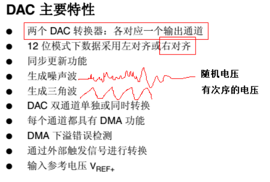
STM32----DAC (digital-to-analog converter)
Article Directory Preface 1. Overview 2. Main features 3. Hardware connection 1. Used PA4 and PA6 pins 2. Example of connection schematic diagram of PA4 and PA6 pins 4. Source code download Summarize ...
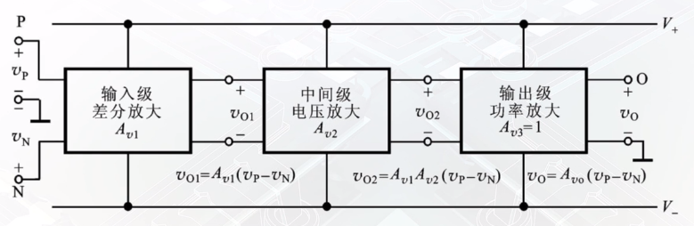
Analog Digital Circuit -> Operational Amplifier
Operational Amplifier Integrated circuit operational amplifier Ideal operational amplifier Non-inverting amplifier circuit Voltage follower Inverting amplifier circuit Difference circuit Instrument am...
Digital-to-analog circuit content conjecture
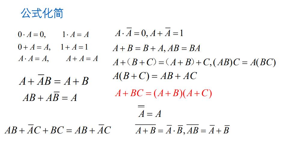
Digital-to-analog electrical part original intention disclaimer Digital RAM ROM problem Conversion between bases Logical expression simplification Differentiate between various logic gates AD problem ...
More Recommendation

Example Modelica - Interface mechanism
Modelica libraries of institutions ( Mechanics) Contains three sub-libraries: 1) MultiBody, Mainly for three-dimensional modeling means; 2) RotationalMainly used for one-dimensional model of the rotar...


Example Modelica - bridge rectifier
Bridge rectifier, English BRIDGE RECTIFIERS, also known asBridge rectifier, Continuity is unidirectional with a diode for rectifying the most common circuits used to converts AC power to DC power. Cir...

DSP TMS320F280049 learning digital-to-analog converter DAC
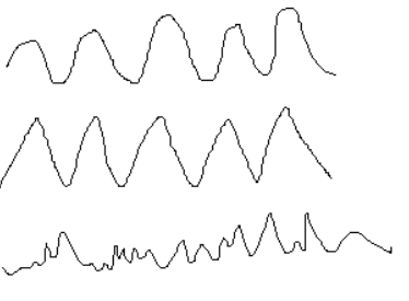
The F280049C contains two 12-bit DAC cores, DACa and DACb, which can generate a variety of waveforms, such as sine, square, and sawtooth. Optional internal reference source 1.65V or 2.5V, external ref...

ADC analog to digital converter (parallel comparison type)
Success is not only the future, but decided to do the moment, continued accumulation. I chose the topic is class-based ADC, Topics requirements: Input:0 ~5VDC, Output: sixTTL Level, Conversion rate: &...