WiFi-ESP8266 entry development (13)-using SPI
Note: Those who are interested in ESP8266 open source technology can join a group. Let’s explore, exchange and learn together. Group name: ESP8266 open source technology exchange group.
Introduction
Serial Peripheral Interface (SPI) is a bus interface connection protocol initiated by Motorola.
- The SPI interface uses four wires for communication. Therefore it is also called the four-wire serial communication protocol.
- SPI is a full-duplex master-slave communication protocol. This means that only one master station and one slave station can communicate on the interface bus at the same time.
- SPI-enabled devices work in two basic modes of SPI operation, namely SPI master mode and SPI slave mode.
- The master device is responsible for initiating communication. The master device generates the serial clock for synchronous data transfer. The master device can process multiple slave devices on the bus by selecting the bus one by one.
The ESP8266 based on NodeMCU has hardware SPI, with 4 pins that can be used for SPI communication. Through this SPI interface, we can connect any device that supports SPI to NodeMCU and communicate with it.
The SPI pins (SD1, CMD, SD0, CLK) of ESP8266 are specifically used for Quad-SPI communication with ESP-12E flash, so they cannot be used for SPI applications. We can use the hardware SPI interface for user-side applications.
The figure below shows the four SPI interface pins used internally for flash. It includes four I/O (4-bit data bus) with synchronous clock (SDIO_CLK) and chip select pin (SDIO_CMD), that is, four (SDIO_DATA0-SDIO_DATA3) bidirectional (I/P and O/P) data signals. It is mainly used to obtain more bandwidth/throughput than dual I/O (2-bit data bus) interfaces.
NodeMCU SPI pins
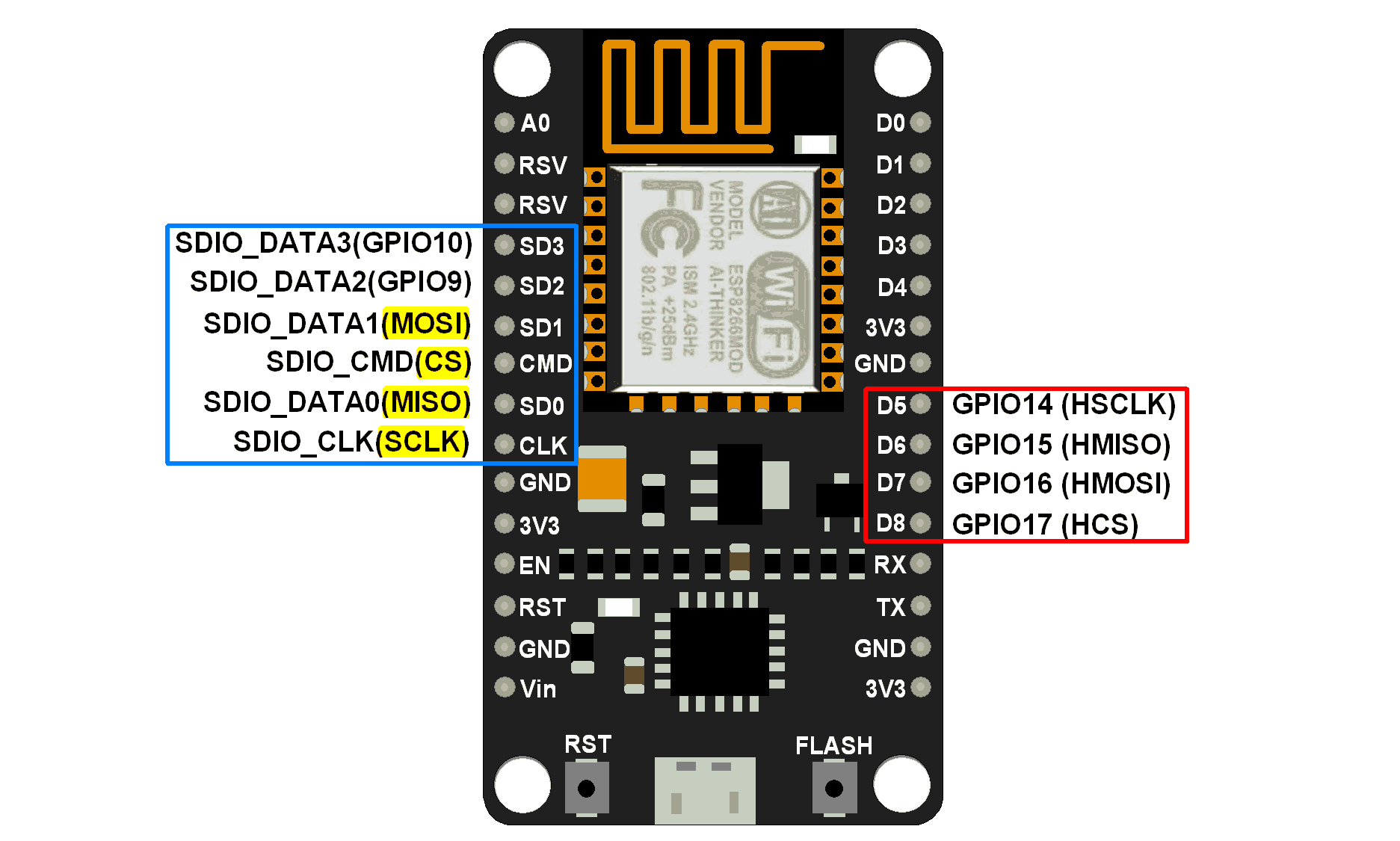
NodeMCU SPI pins
MISO(Master In Slave Out)
The master receives data, and the slave transmits data through this pin.
MOSI(Master Out Slave In)
The master sends data, and the slave receives data through this pin.
SCLK (serial clock)
The master generates this clock for the communication used by the slave.
Only the master can start the serial clock.
CS (Chip Select)
The host can select the slave through this pin and start communicating with it.
example
Let's write an Arduino sketch of SPI communication for NodeMCU. Here NodeMCU is the master device, and we use Arduino as the slave device.
In this example, we send the "Hello Slave" string as the end "\n" of the string from the NodeMCU master. The slave device receives the string and prints it on the serial monitor.
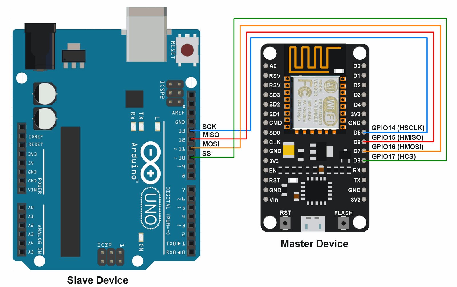
NodeMCU Arduino SPI interface diagram
Arduino program for NodeMCU main SPI
#include<SPI.h>

char buff[]="Hello Slave\n";

void setup() {
 Serial.begin(9600); /* begin serial with 9600 baud */
 SPI.begin();  /* begin SPI */
}

void loop() {
 for(inti=0; i<sizeof buff; i++)  /* transfer buff data per second */
  SPI.transfer(buff[i]);
 delay(1000);
}
Arduino Uno slave SPI Arduino program
#include <SPI.h>

char buff [100];
volatile byte index;
volatile bool receivedone;  /* use reception complete flag */

void setup (void)
{
  Serial.begin (9600);
  SPCR |= bit(SPE);         /* Enable SPI */
  pinMode(MISO, OUTPUT);    /* Make MISO pin as OUTPUT */
  index = 0;
  receivedone = false;
  SPI.attachInterrupt();    /* Attach SPI interrupt */
}

void loop (void)
{
  if (receivedone)          /* Check and print received buffer if any */
  {
    buff[index] = 0;
    Serial.println(buff);
    index = 0;
    receivedone = false;
  }
}

// SPI interrupt routine
ISR (SPI_STC_vect)
{
  uint8_t oldsrg = SREG;
  cli();
  char c = SPDR;
  if (index <sizeof buff)
  {
    buff [index++] = c;
    if (c == '\n'){     /* Check for newline character as end of msg */
     receivedone = true;
    }
  }
  SREG = oldsrg;
}
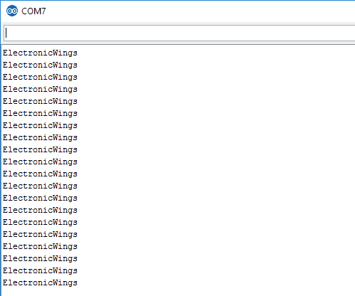
Slave output window
The output is received on the slave device sent from the master device.
Intelligent Recommendation
WiFi-ESP8266 entry development (1)-Arduino environment construction
Those who are interested in ESP8266 open source technology can join a group. Let’s explore, exchange and learn together, group number: 579932824. Group name: ESP8266 open source technology excha...

WiFi-ESP8266 entry development (eighteen)-WiFi connection PC control, TCP/UDP
Note: If you are interested in the ESP8266 open source technology, you can add groups. Let's explore exchange and study together, group number: 579932824. Group name: ESP8266 open source techno...

STM32CubeMx development road-13 using SPI to read and write W25Q64
STM32CubeMx development road-13 using SPI to read and write W25Q64 Operating environment Windows10 STM32CubeMX Version 5.2.0 Keil5(MDK5) Version 5.28.0.0 Introduction This routine mainly explains how ...

WiFi-ESP8266 entry development (19) - mobile phone APP control and transparent transmission
Note: If you are interested in the ESP8266 open source technology, you can add groups. Let's explore exchange and study together, group number: 579932824. Group name: ESP8266 open source techno...
hspi development of stm32 connected to esp8266 through spi
Stm32 connects to esp8266's hspi development via spi I have just done the development of stm32 connecting to esp8266 through spi. At present, most of the problems encountered have been solved. Basical...
More Recommendation

IoT development 13 FAQs for ESP8266
Basic concepts related What is ESP8266? ESP8266 is a high-performance wireless SOC. It integrates the industry-leading Tensilica L106 ultra-low power 32-bit micro MCU in a smaller package with 16-bit ...

How does Arduino drive an OLED12864 display? (using the U8G2 library, the actual master is ESP8266 using ArduinoIDe development, SPI interface)
First, introduction We have successfully driven LCD12864 and LCD1602, which we drive OLED12864. What is the difference between OLED and LCD? Mainly the difference in illumination, each pixel point of ...
A53 development board - WIFI (ESP8266) application example
First you need to have detailed information on ESP8266 to understand the mode and AT command. Detailed comments in the rest of the code...
Making WiFi killer with esp8266 development board
1. Obtain the esp8266 development board [ESP8266 serial wifi module NodeMCU Lua V3 IoT development board CH340] https://m.tb.cn/h.eHbzj6H?sm=3f959b I use this, Taobao can buy it, about 14 yuan. Second...
wemos D1 wifi ESP8266 development board
Reference tutorial: arduino install WeMos d1 board support --- electric lamp operation Smart home voice control: Amazon Echo + NodeMCU (ESP8266 analog Wemo) control LED https://github.com/kakopappa/ar...