Multisim simulation current control voltage source circuit connection method
tags: multisim simulation experience sharing
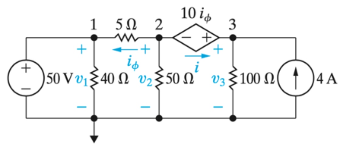
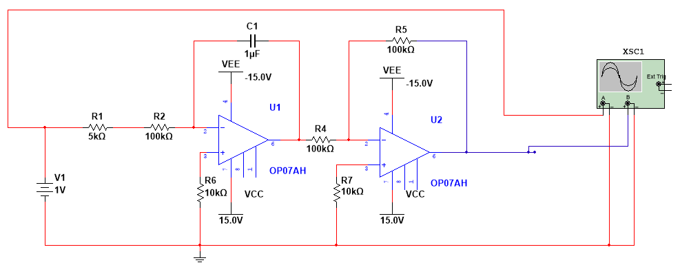
Original circuit diagram:
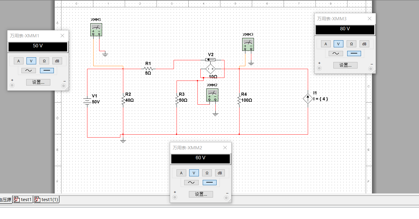
Multisim simulation process (verify super node method):
summary:
1. Pay attention to the connection method of the current control voltage source, which is to connect the current source at the input end into the control end in series, then connect the input end to the output end in series, and use the output terminal connected to the output end as the corresponding output terminal in the circuit diagram. Correspondingly, the input terminal of the input end serves as the corresponding input terminal in the circuit diagram.
2. The mutual resistance coefficient is equal to the voltage value at both ends of the controlled source divided by the current value in the circuit diagram.
References:
https://www.zhihu.com/question/467234597
https://www.zhihu.com/question/397518834
Intelligent Recommendation
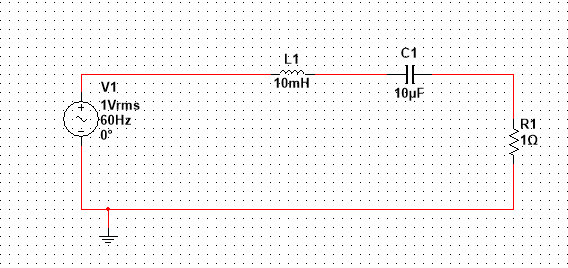
Resonant circuit schematic and simulation multisim
Resonant circuit schematic and simulation What is Used to do personal notes, may be wrong What is If the voltage and current in phase with the port circuit having capacitance and inductance, the shape...
Simulation of zcs circuit based on multisim
Simulation of zcs circuit based on multisim Today, my junior’s graduation project requires simulation of analog circuits, so I took out the multisim software I learned in the university and used...

Multisim optocoupler relay simulation circuit
Start getting in touch with Multisim, and then make some simple simulation circuits, and record some problems and solutions here. question: 1. R1 initially used a 1k resistor, but the light below did ...
Multisim14.0 circuit simulation and display the voltage current of each node and branches
Table of contents Circuit simulation and display voltage current of each branch branch Results analysis Show node labeling to view each node voltage Circuit simulation and display voltage current of e...
[Multisim Simulation] Simulation of second -order source high -pass filter circuit simulation
[Multisim Simulation] Simulation of second -order source high -pass filter circuit simulation Multisim simulation The second -order active high -pass filter circuit, T is about 500US, the gain is clos...
More Recommendation

[Multisim Simulation] Simulation of full -wave rectifier circuit
[Multisim Simulation] Simulation of full -wave rectifier circuit Multisim simulation demonstration The left circuit is a virtual circuit Simulation waveform Connection description The GND pins of the ...

[Multisim simulation] Diode piping circuit simulation
[Multisim simulation] Diode piping circuit simulation Top clamp circuit Instructions This circuit is a clamp circuit that turns the bottom (zero level) into the bottom (zero level) into the rectangula...
Pspice integration circuit simulation problem summary (voltage-controlled voltage source simulation ideal op amp)
Pspice integration circuit simulation problem summary (voltage-controlled voltage source simulation ideal op amp) Summary: 1. How to simulate an ideal op amp with a voltage-controlled current source; ...
Note about the oscilloscope without integration curve when multisim simulation integration circuit (automatic control experiment)
Note about the oscilloscope without integration curve when multisim simulation integration circuit (automatic control experiment) 1. Problems encountered Recently, in the simulation process of the aut...
Multisim oscillator frequency electronic circuit simulation 4.7
Multisim oscillator frequency electronic circuit simulation 4.7 Version Multisim14.1 Inductive three-point oscillator Feature Suitable inductive three-point oscillator in a low frequency, the capacito...