Detailed explanation of TCP/IP packet structure
tags: Network structure model
Generally speaking, we only need to call some encapsulated functions or components to complete most of the work in network programming, but in some special cases, we need to deeply understand the structure of network data packets and protocol analysis. Such as: network monitoring, troubleshooting, etc...
IP packets are insecure, but they are the basis of the Internet and have a wide range of applications. There are more than 10 kinds of protocol families derived from the IP protocol (as far as I know), and more IP-based protocols will appear in the future...
Let's start with the actual situation first!
Generally speaking, when we talk about the speed of Internet access, we use bandwidth to describe it professionally. In fact, regardless of the speed or bandwidth of the Internet, it is inaccurate. For example: 1 trillion, 512K... Some students at school may have questions, obviously my business is 1M, why can't the download speed soar to 100K? Why does 512K capped more than 50K? …
The 1M mentioned here refers to 1Mbps = 1 Million Bits Per Second, which is 1M bits per second, that is, 1048576 binary bits are transmitted in one second. We know that a byte is 8 binary bits.
Okay, here comes the question. Even so, 1M=1048756÷8=131072÷1024=128K. That should also be 128K, why the download speed is still very small to 120K, 110K are thankful. After reading this article, your account is right...
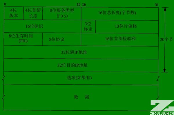
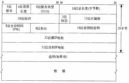
IP packet structure:
As shown in the figure, one scale represents 1 binary bit (bit).
1-1. Version 4 digits, indicating the version number, currently the most widely used is 4=B1000, which is often referred to as IPv4; I believe IPv6 will be widely used in the future, and it can assign an IP address to each button in the world.
1-2. The length of the header is 4 bits, and the length of the packet header. It indicates how many 32-bit long integers are included in the packet header, that is, how many 4-byte data. No option is 5 (red part).
1-3. Service type, including 8 binary bits, the meaning of each bit is as follows:
Process field: 3 bits, set the importance of the data packet, the larger the value, the more important the data, the value range is: 0 (normal) ~ 7 (network control)
Delay field: 1 bit, value: 0 (normal), 1 (very low delay)
Traffic field: 1 bit, value: 0 (normal), 1 (extra high traffic)
Reliability field: 1 bit, value: 0 (normal), 1 (very high reliability)
Cost field: 1 digit, value: 0 (normal), 1 (special minimum cost)
Reserved field: 1 bit, unused
1-4. The total length of the package is 16 bits. The total length of the current data packet is in bytes. Of course, the maximum can only be 65535, and 64KB.
2-1. Reorganization identifier 16 bits, sending the identifier given by the host so that the receiver can perform fragment reassembly.
2-2. The 3 flags, their respective meanings are as follows:
Retained segment (2): 1 bit, unused
Non-fragmented bit (1): 1 bit, value: 0 (datagram segmentation allowed), 1 (datagram cannot be segmented)
More segments (0): 1 bit, value: 0 (there is no packet after the data packet, the packet is the last packet), 1 (there are more packets after the data packet)
2-3. The segment offset is 13 bits, which is combined with more segment bits to help the receiver combine the segmented messages, in bytes.
3-1. The survival time is 8 bits. This is the TTL (Time To Live) that is often seen by the ping command. Each time it passes a router, the value is decreased by one to zero and discarded.
3-2. The 8-bit protocol code indicates that the upper layer protocol of the package is used, such as TCP=6, ICMP=1, UDP=17, etc.
3-3. The header checksum is 16 bits, which is the checksum of the IPv4 packet header.
4-1. The source address, 32 bits and 4 bytes. The IP we often see is to separate each byte with a dot (.), that's all.
5-1. Destination address, 32 bits, same as above.
6-1. Optional options are mainly used for special situations. Often, secure routing will be filtered out as an attack. TP-LINK's TL-ER5110 routing can do this.
7-1. User data.
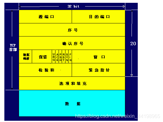
TCP packet structure:
1-1. The source port is 16 bits, and the range is of course 0-65535.
1-2. Destination port, same as above.
2-1. The data sequence number is 32 bits. TCP codes a number for each byte sent. Here, the sequence number of the first byte of the current packet data is stored.
3-1. Confirm the sequence number is 32 bits. For security, TCP tells the receiver that he wants the sequence number of the first byte of the data packet received next time.
4-1. Offset by 4 bits, similar to IP, indicating how many 32 bits the data is from the packet header.
4-2. Reserved 6 bits, unused, should be set to zero.
4-3. Urgent bit URG—When URG=1, it indicates that the urgent pointer field is valid. It tells the system that there is urgent data in this segment, which should be transmitted as soon as possible (equivalent to high priority data).
4-3. Acknowledgment bit ACK—The acknowledgment number field is valid only when ACK=1. When ACK=0, the confirmation number is invalid.Refer to TCP three-way handshake
4-4. Reset bit RST (Reset)-When RST = 1, it indicates that there is a serious error in the TCP connection (such as due to host crash or other reasons), you must release the connection, and then re-establish the transport connection.Refer to TCP three-way handshake
4-5. Synchronization bit SYN—When the synchronization bit SYN is set to 1, it indicates that this is a connection request or connection acceptance message.Refer to TCP three-way handshake
4-6. Termination bit FIN (FINal)-used to release a connection. When FIN=1, it indicates that the data of the sending end of this segment has been sent, and the transport connection is required to be released.
4-7. The window field is 16 bits. The window field is used to control the amount of data sent by the other party in bytes. One end of the TCP connection determines its own receiving window size according to the set buffer space size, and then notifies the other party to determine the upper limit of the other party's sending window.
5-1. Packet checksum 16 bits, includingcapitalwithdataThese two parts. When calculating the checksum, a 12-byte pseudo header is added before the TCP segment.
5-2. Emergency pointer 16 bits, the emergency pointer indicates the sequence number of the last byte of emergency data in this message segment.
6-1. 24-bit optional option, similar to IP, is an optional option.
6-2. Fill in 8 bits to make the option 32 bits.
7-1. User data...
It can be seen that each IP packet requires a header length of at least 20 bytes. These are not related to the download content. Plus most of the current transmissions, including the http protocol (that is, IE direct download), are based on the TCP protocol, so the IP package It is also necessary to deduct the 20-byte TCP header from the user data, which is already 40 bytes, plus the connection of other programs, status confirmation and other packages, so the calculation is smaller than the theoretical value.
In addition, the network environment (including the stability factor and the forwarding rate of the transmission node) is also an important reason for affecting the download speed...
"Linux high-performance server programming" reading notes:
1. TCP/IP packet flow
(1) The data encapsulated by TCP/UDP is called TCP segment/UDP datagram. Because the TCP protocol not only maintains a connection for both parties to the communication, but also has the function of timeout retransmission, the operating system stores the data to be sent by the APP in the relevant data structure of the kernel:


The figure above describes the schematic diagram when TCP sends data, as does the receive buffer. When the sender APP calls the system call send()/write() function to write data to the TCP connection, the TCP module in the kernel first copies the APP data to the TCP kernel send buffer corresponding to the connection, and then the TCP header information The data in the TCP send buffer is passed to the IP module in the kernel, using the services provided by the IP module.
For UDP sending data, the encapsulation process is similar to TCP. The difference is that because UDP provides an unreliable service, the UDP kernel module does not save a copy of the APP data. When the data in the send buffer is sent out , The data in the buffer is discarded. Of course, if the APP wants to implement overtime retransmission, it is necessary to copy the data back to the UDP send buffer in the kernel space in the APP. In addition, since UDP is based on connectionless communication, the sender sends data using the function sendto() to indicate the address information of the receiver. Of course, this is not absolute. The exception is when using the bind() function. You can read the use of send(), sendto(), recv(), and recvfrom() in detail.
(2) Next, the IP-encapsulated data is called an IP datagram, and the data segment in the IP datagram is UDP datagram/TCP datagram segment/ICMP datagram.
(3) The data encapsulated by the data link layer is called a frame. Depending on the transmission medium, the types of frames are also different, such as Ethernet frames and token ring frames. Taking an Ethernet frame as an example, its encapsulation format is:

Frame data is a sequence of bytes that is ultimately transmitted on the physical network. It should be noted that the maximum transmission unit (MTU, Max Transmit Unit) of the frame, that is, the maximum number of upper layer protocol data (such as IP message segments) that the frame can carry will be limited by the network type. The MTU of the Ethernet frame is 1500 Bytes, and the IP segments that are too long may need to be transmitted in packets.
2. TCP/IP unpacking process
As shown in the figure, when the frame data arrives at the destination host, it will be transmitted in sequence along the protocol stack from bottom to top. Each layer of the protocol in turn obtains the required data according to the header information responsible for this layer in the frame, and finally hands the processed frame to the target APP. I understand that this is an unpacking process.

(1) The IP protocol, ARP protocol and RARP protocol all use frames to transmit data, so the header of the frame needs to provide fields to distinguish them. Taking Ethernet as an example, it can be seen in its frame format. It uses a 2-byte type field to represent the upper layer protocol: if it is 0x800, the data portion of the frame is an IP datagram, and the Ethernet driver will deliver the IP datagram to IP module. If the type field is 0x806, the data part of the frame is the ARP request/response report, which will be delivered to the kernel's ARP module. Unpacking needs to depend on the type field in the header information.
(2) In the same way, ICMP/UDP/TCP all use IP protocol, so the header of the IP packet uses 16-bit fields to distinguish.
(3) TCP/UDP packets distinguish the upper layer APP by the 16-bit port number in the header. For example, the port number occupied by the DNS protocol is 53, and the port number occupied by the HTTP protocol is 80.
After reaching the application layer, the APP (or ARP service, RARP service, ICMP service) will receive the source application data before being encapsulated by the operating system. So from the APP's perspective, unpacking/packing does not seem to have happened.
Intelligent Recommendation
Detailed explanation of the whole process of IP data packet transmission-how is the data encapsulated in each layer of tcp/ip?
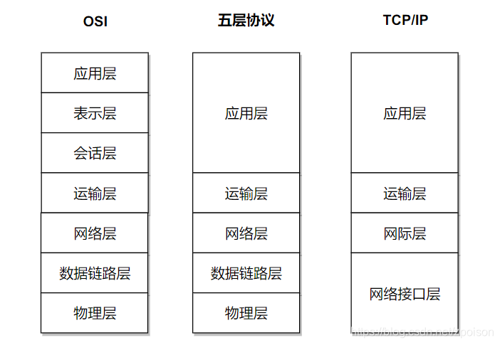
We know that the current TCP IP protocol used in the Internet is based on the OSI (Open System Interconnection) seven-layer reference model, (though not completely consistent) from top to bottom, the ...
Detailed explanation of the whole process of IP data packet transmission-how the data is sealed at each layer of tcp/ip
We know that the current TCP/IP protocol used in the Internet is based on the OSI (Open System Interconnection) seven-layer reference model, (although not completely consistent) from top to bottom, re...

TCP/IP----TCP detailed explanation
TCP/IP protocol----It is a network communication model and an entire network transmission protocol family, which is the basic communication architecture of the Internet. It is often referred to as the...

"TCP/IP Detailed Explanation Volume 2" Notes: mbuf structure
A basic concept in the BSD TCP/IP protocol stack code design is the memory cache, called ambuf, Used to store various information. The main purpose of mbuf is to save user data passed between processe...
Detailed explanation of TCP sticky packet problem handling
tcp sticky package problem handling The agreement structure of the above figure, let's take a millet: 1. We received a complete protocol string as hex code: 2. The corresponding disassembly, each valu...
More Recommendation
Detailed explanation of TCP sticky packet problem
Detailed explanation of TCP sticky packet problem Article Directory Detailed explanation of TCP sticky packet problem I. Introduction 2. Introduction to TCP protocol 3. Protect message boundaries and ...
TCP / IP packet header structure finishing
IP protocol is the driving force TCP / IP protocol suite that provides stateless upper layer protocols, connectionless, unreliable service. Advantages: simple and efficient. Stateless means: status IP...
Detailed explanation of TCP, UDP, and IP
I. Computer Network Architecture 1.1 Protocols for different network layers 1.2 Introduction to System Hierarchy Five-layer protocol Application layer: Provides data transfer services for specific app...
Detailed explanation of TCP/IP protocol
Why is there a TCP/IP protocol Around the world, a variety of computers run different operating systems for everyone. The methods used by these computers to express the same information vary widely. I...

TCP/IP Detailed Explanation--Overview
Network protocols are usually developed at different levels, and each layer is responsible for different communication functions. A protocol family, such as TCP/IP, is a group of multiple protocol com...