DOIP--Detailed 2
tags: Internet of Vehicles & Ethernet Ethernet DOIP
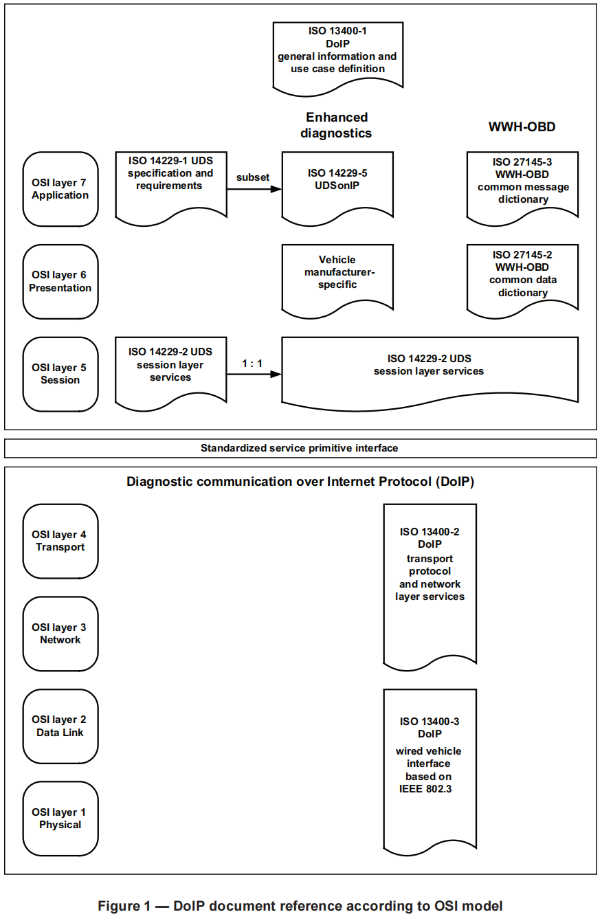
First, let's introduce the vehicle network architecture that supports ethernet and DoIP.
Schematic diagram of vehicle network architecture with ethernet node
The above picture briefly describes the association between the vehicle network with ethernet nodes and the test equipment in the external network. In the vehicle network, there must be one and only one DoIP edge node gateway, which serves as the only interface of the car to the external diagnostic equipment. In addition, there may be the following types of nodes:
- Support DoIP, at the same time as a gateway, there are sub-networks behind it
- Does not support DoIP, but supports ethernet communication
- Does not support ethernet, so it is impossible to support DoIP
For external test equipment, they must only be directly connected to and communicate with the DoIP edge node gateway, and the communication with other ECUs in the vehicle network must be routed by the DoIP edge node gateway.
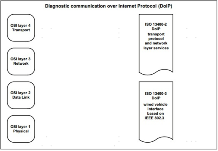
Data link layer and physical layer
According to the requirements of ISO-13400, DoIP communication supports 100BASE-TX (100 Mbit/s Ethernet) and 10BASE-T (10 Mbit/s Ethernet) at the physical layer. The MAC address of the DoIP device also meets the requirements of IEEE 802.3.
Transport layer and network layer
ISO-13400 stipulates that DoIP communication must support both UDP and TCP at the transport layer, and defines the use cases of UDP and TCP, as well as the port number used. A little more detailed description later.
ISO-13400 stipulates that DoIP communication uses IPv6 on the network layer, but for backward compatibility reasons, IPv4 is also supported. In addition, for IPv4, it is necessary to support the Address Resolution Protocol (ARP), and for IPv6, it is also necessary to support the Neighbor Discovery Protocol (NDP). These two protocols are used to obtain the MAC address when only the IP address is known. of.
DoIP data format
DoIP data format
The figure above shows the data format of DoIP. In DoIP technology (1), we have briefly introduced the five parts of DoIp data. The data of the fifth part can be further subdivided into three parts.
- Source address, identifying who sent the data
- Destination address, identifying who received the data
- Diagnostic command, that is, specific diagnostic request or response defined in UDS or OBD
In this article, I will give examples of the value ranges of these parts of data:
The first two parts of the DoIP data are the DoIP version and the DoIP version inverted bit by bit. The value range of the DoIP version is as follows:
0x00: reserved
0x01: DoIP ISO/DIS 13400-2:2010
0x02: DoIP ISO 13400-2:2012
0x03…0xFE: reserved by this part of ISO 13400
0xFF: default value for vehicle identifcation request messages
The third part of DoIP data is data type, which describes the data type in the data packet. The value range is shown in the following figure:
Overview of DoIP data types
The above table not only defines the values representing different data types, but also explains whether the specific data type should be sent via UDP or TCP, and defines which port should be sent on.
The most commonly used data types should be 0x8001, 0x8002, and 0x8003, which represent diagnostic messages, positive responses to diagnostic messages, and negative responses to diagnostic messages.
0x0001 to 0x0004 are used for car identification report or request. This kind of command can only be sent through UDP message, which is mainly used for the vehicle discovery process after the car and the diagnostic instrument enter the network and before the diagnosis connection is established.
Routing activation request and response identified by 0x0005 and 0x0006 are used to request diagnostic communication after the socket is established.
0x0007 and 0x0008 are used for Alive check to check whether the currently established diagnostic connection socket is still in use. If it is no longer in use, close the socket to release resources.
The third part of the DoIP data is the data length. This is very simple, which is to identify how much user data is behind.
The fifth part of the DoIP data is very simple. It is used to identify the sender and receiver of the data, as well as specific diagnostic data.
The following figure is an example of the complete structure of DoIP data:
Example of complete structure of DoIP data
byte 0: ISO13400 version
byte 1: ISO13400 version is reversed bit by bit
byte 2~3: data type, 0x8001, indicating that this is a data packet of diagnostic information
byte 4~7: data length, the value in this example is 7, which means there are 7 bytes of data behind
byte 8~9: source address
byte 10~11: destination address
byte 12~13: specific diagnostic command, SID is 22, which means read, DID is 0xF8 10
This data segment is passed to the lower layer protocol as an SDU, encapsulated layer by layer into a complete Ethernet frame and sent out.
to sum up:
This article mainly introduces the structure of DoIP data, that is, what does each byte position of DoIP data mean. In the next article, I will introduce the management of the diagnostic logic connection inside the DoIP node and the establishment of DoIP communication.
Intelligent Recommendation
DoIP (I) - Basic Concept
1. DoIP Overview DoIP (Diagnostic communication over Internet Protocol) is a diagnosis based on vehicle Ethernet. It belongs to the transmission layer in the OSI layer seven model. The diagnostic data...

[Car Ethernet] [DoiP] Ethernet Diagnostics Service DoiP Protocol Analysis
table of Contents Preface: DoIP is an important part of the vehicle Ethernet communication. This article mainly introduces the ISO13400 related link layer, network layer, transport layer related proto...

Establishment of doip communication process (1)
Doip node forwards uds messages—Ecu feedback uds messages—Doip node messages to doip format is sent—External test equipment Table of contents 1. DoIP entity internal management diagn...
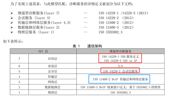
Interpretation of ISO 13400 (DoIP) standard
The urgent need for transmission bandwidth of automotive electronic systems has promoted the development of in-vehicle Ethernet technology. DoIP (Diagnostic communication over Internet Protocol) is bo...
Car Ethernet study notes 3-DOIP protocol
ISO 14229-1:2013 Road vehicles - Unified Diagnostic Services (UDS)Part1: Specification and requirements; ISO 14229-2:2013 Road vehicles - Unified Diagnostic Services (UDS)Part 2: Session layer service...
More Recommendation
UDS Diagnostics-DOIP and Ethernet Protocol Relationship
DoIP technology: UDS diagnosis service, vehicle diagnosis through TCP/IP and Ethernet, the protocol is defined inISO 13400。 ISO13400 involves mainly distributed in the four layers of the transmission ...
DOIP remote diagnosis and comparison with UDSONCAN - APAUTOSAR_DOIP001
1 What is doip? DoiP (Diagnostic Communication over Internet Protocol is based on Ethernet 100 Base-TX Diagnostic Protocol (100Basetx IS A Type Of Standard for Implementing Fast Ethernet Networks, wit...

doip diagnostic session - routing activation analysis
Table of contents 1. Activate the request (0x0005) 2. Activate the response (0x0006) 3. Routing activation phase (after vehicle identification phase) 4.Route activation type 1.Activatio...
DoIP flashing of automotive Ethernet application case-let data "fly"
With the rapid development of chip technology, Ethernet technology has gradually entered the automotive industry, and the functions that can be achieved by on-board controllers have become more and mo...