GDT (Global Descriptor Table) and LDT (Local Descriptor Table)
Each program has its own LDT, but all programs on the same computer share a GDT. LDT describes the segment local to each program, including its code, data, stack, etc. GDT describes the system segment, including the operating system itself.
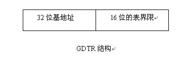
①Global Descriptor Table (GDT)In the entire system, there is only one global descriptor table GDT (one processor corresponds to one GDT). GDT can be placed anywhere in memory, but the CPU must know the entry of the GDT, that is, where the base address is placed, Intel ’s The designer door provides a register GDTR to store the entry address of the GDT. After the programmer sets the GDT at a certain location in the memory, the entry address of the GDT can be loaded into this accumulator through the LGDT instruction. From then on, the CPU According to the content of this register as a GDT entry to access the GDT. What GDTR stores is the base address of GDT in memory and its table length limit.
 ②Segment selector (Selector)Access to the global descriptor table by GDTR is done through the "segment selector" (segment register in real mode). In order to access a segment, a Pentium program must load the selector of this segment into one of the 6 segment registers of the machine. During operation, the CS register holds the selector of the code segment, and the DS register holds the selector of the data segment. Each selector is a 16-digit number.
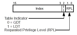 One of the selectors indicates whether the segment is local or global (whether it is in LDT or GDT), the other 13-bit index is the entry number of the LDT or GDT, indicating that the required segment descriptor is The location of the descriptor table. From this location, the corresponding descriptor can be found based on the base address of the descriptor table stored in GDTR, and then the OFFSET of the segment in the descriptor table plus the logical address (SEL: OFFSET) It can be converted into a linear address. Therefore, the length of these tables is limited to accommodate up to 8K segment descriptors.
The TI value in the segment selector is only one bit 0 or 1. 0 means that the selector is selected in GDT, and 1 means that the selector is selected in LDT. The request privilege level (RPL) represents the privilege level of the selector. There are 4 privilege levels (Level 0, Level 1, Level 2, Level 3). Each segment in the task has a specific level. Whenever a program tries to access a certain segment, the privilege level possessed by the program is compared with the privilege level to be accessed to decide whether the segment can be accessed. The system agrees that the CPU can only access segments of the same or lower privilege level.
For example, given a logical address: 21h: 12345678h converted to a linear address
a. selector SEL = 21h = 0000000000100 0 01b what he represents means: the index = 4 of the selector is 100b to select the fourth descriptor in GDT; TI = 0 represents the selection The child is selected in GDT; 01b at the back left represents the privilege level RPL = 1
b. OFFSET = 12345678h If the segment base address (Base) described in the fourth descriptor of GDT at this time is 11111111h, the linear address = 11111111h + 12345678h = 23456789h
③Local Descriptor Table (LDT)There can be several local descriptor tables, one for each task. We can understand GDT and LDT in this way: GDT is the first-level descriptor table, and LDT is the second-level descriptor table. As shown
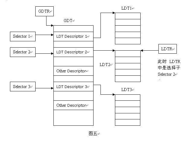
LDT and GDT are essentially the same, but LDT is nested in GDT. LDTR records the starting position of the local descriptor table. Unlike GDTR, the content of LDTR is a segment selector. Since LDT itself is also a segment of memory, it is also a segment, so it also has a descriptor describing it. This descriptor is stored in the GDT, and there will be a selector corresponding to this descriptor. LDTR loads such a selector. LDTR can be changed at any time in the program by using the lldt instruction. As shown in the figure above, if the Selector 2 is loaded, the LDTR points to the table LDT2. For example: if we want to select the address 12345678h of the segment described in the third descriptor in the table LDT2.
1. First, you need to load LDTR to point to LDT2. Use the command lldt to load Select2 to LDTR
2. When accessing through a logical address (SEL: OFFSET), SEL index = 3 means to select the third descriptor; TI = 1 means that the selector is selected in LDT, and LDTR points to It is LDT2, so it is selected in LDT2, at this time the SEL value is 1Ch (binary is 11 1 00b). OFFSET = 12345678h. The logical address is 1C: 12345678h
3. The descriptor is selected by SEL, and the linear address can be obtained from the base address (Base) in the descriptor plus OFFSET, for example, the base address is 11111111h, then the linear address = 11111111h + 12345678h = 23456789h
4. If you want to access the third descriptor in LDT1 at this time, just use the lldt instruction to load the Selector 1 and then perform steps 2 and 3 (because At this time, LDTR points to LDT1)
Because each process has its own set of program segments, data segments, and stack segments, with the local descriptor table, each process segment, data segment, and stack segment can be Encapsulated together, as long as you change the LDTR, you can achieve access to segments of different processes.
Segment descriptor:
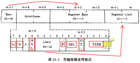
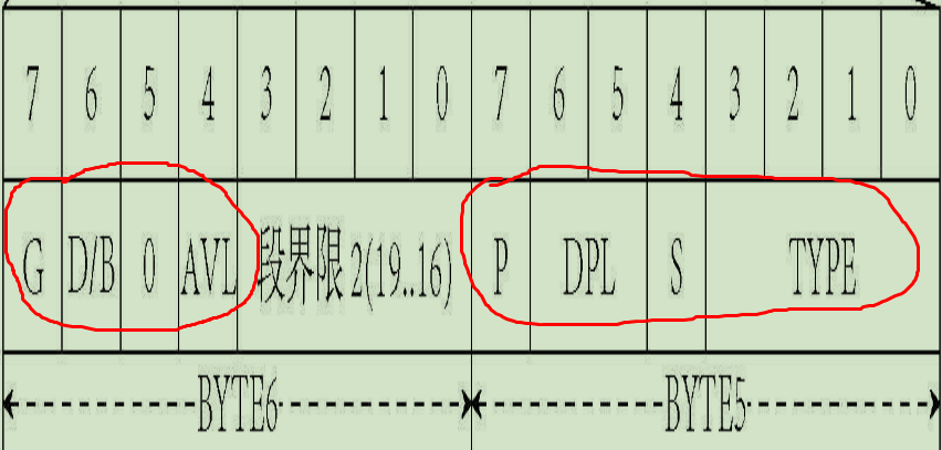
P, present bit, 1 means the described segment exists (valid), 0 means the described segment is invalid, using this descriptor will cause an exception
DPL, Descriptor privilege, descriptor privilege level, indicating the privilege level of the described segment
DT, descriptor type bit, 1 indicates that the current descriptor is a storage segment descriptor, and 0 is a system descriptor or gate descriptor.
TYPE:
Bit 0: A (accessed) bit, indicating whether the descriptor has been accessed; when the selector is loaded into the segment register, this bit is marked as 1.
Bit 3: E (EXECUTABLE?) Bit, 0 indicates that the described segment is a data segment; 1 is an executable segment (code segment)
When it is a data segment,
Bit 1 is the W bit, indicating whether the data segment is writable (0 read-only, 1 writable)
Bit 2 is the ED bit, indicating the direction of expansion of the segment (0 to high bit extension, 1 to low bit extension)
When it is an executable segment,
Bit 1 is the R bit, indicating whether the execution section is readable (0 only execution, 1 readable)
Bit 2 is the C bit, 0 means the segment is not a consistent code segment (common code segment), 1 is a consistent code segment
G is the granularity bit, 0 means LIMIT granularity is byte, 1 is 4K byte.
D position:
1. In the executable section, D is 1, which means use 32-bit address, 32 / 8-bit operand; 0 means use 16-bit address, 16 / 8-bit operand
2. In the segment descriptor (stack segment?) Addressed by SS, D is 1 to indicate implicit operations (such as PUSH / POP) using ESP as the stack pointer,
Use SP for 0 (implicit operation: segment attribute types USE16 / USE32? 66H, 67H? Are not clearly defined)
3. In the storage segment that expands to low, D is 1, indicating that the upper limit of the segment is 4G; the upper limit is 0 and the limit is 64K
The structure representation of the storage segment descriptor: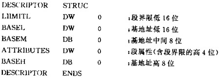
Segment management can convert virtual addresses to linear addresses, while paging management can further convert linear addresses to physical addresses. When the PG bit in CR0 is 1, the paging management function is started. When it is 0, this prohibits the paging management function from being used, and uses the linear address as a physical address.
Convert virtual address to linear address:
Linear address = segment base finger + offset address
Convert 32-bit linear address to physical address:
32 bits are divided into:
Page directory index: occupies the highest 10 bits, indicating the number of page table descriptors in the page directory table
Page table index: 12 to 21 bits, also 10 bits. Indicates the number of page descriptors in this page table
Page descriptor: The lower 12 bits of the linear address are the offset within the page.
3. Examples (very useful for understanding)
1: Visit GDT
Segment descriptor in GDT
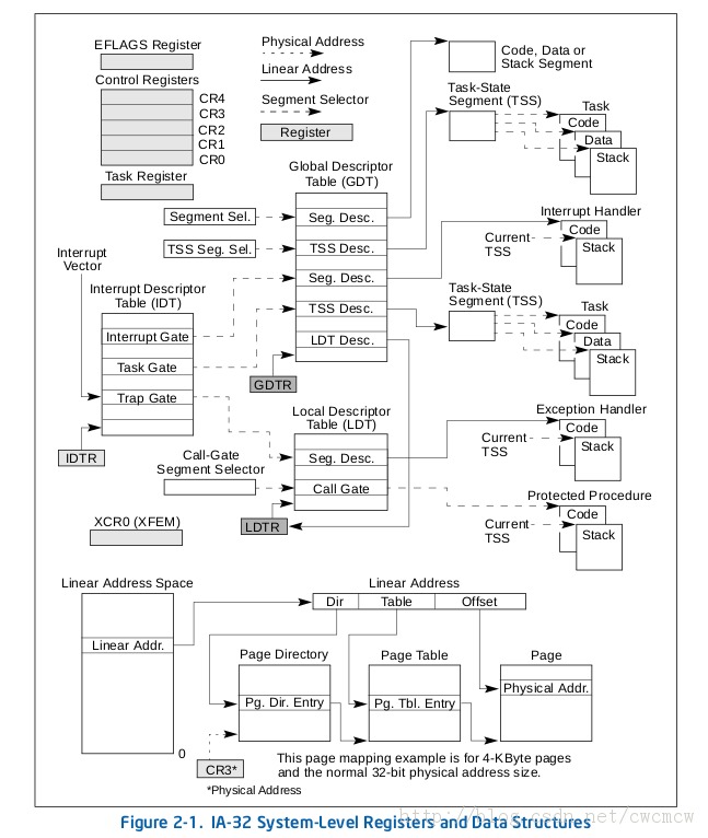
When TI = 0, it means that the segment descriptor is in the GDT, as shown in the figure above:
① First obtain the GDT base address from the GDTR register.
②Then the segment descriptor is obtained with the index value of the upper 13 bits of the segment selector in GDT.
③ The segment descriptor contains various attributes such as the base address, length limit, and priority of the segment. This gives the start address (base address) of the segment, and then adds the base address Only the upper offset address yyyyyyyy can get the last linear address.
2: Visit LDT
Segment descriptor in LDT
When TI = 1, it means that the segment descriptor is in the LDT, as shown above:
① Still get the GDT base address from GDTR register first.
② Get the position index of the segment where the LDT is located from the LDTR register (LDTR high 13 bits).
③ Use this location index to get the LDT segment descriptor in the GDT to get the LDT segment base address.
④ Use the segment selector high 13-bit position index value to get the segment descriptor from the LDT segment.
⑤ The segment descriptor contains various attributes such as the base address, length limit, and priority of the segment. This gives the start address (base address) of the segment, and then adds the base address Only the upper offset address yyyyyyyy can get the last linear address.
Expand
In addition to GDTR and LDTRIDTR and TR
(1) Interrupt descriptor table register IDTR
Similar to GDTR, the IDTR register is used to store the 32-bit linear base address of the interrupt descriptor table IDT and the 16-bit table length value. The instructions LIDT and SIDT are used to load and save the contents of the IDTR register, respectively. After the machine is powered on or the processor is reset, the base address is set to 0 by default, and the length value is set to 0xFFFF.
(2) Task register TR
TRUsed to address a special task status segment(Task State Segment, TSS). The TSS contains important information about the current task.
The TR register is used to store the 16-bit segment selector, 32-bit base address, 16-bit segment length, and descriptor attribute values of the TSS segment of the current task. It refers to a TSS type descriptor in the GDT table. The instructions LTR and STR are used to load and save the segment selector part of the TR register, respectively. When using the LTR instruction to load the selector into the task register, the segment base address, segment limit length, and descriptor attributes in the TSS descriptor are automatically loaded into the task register. When performing task switching, the processor will automatically load the segment selector and segment descriptor of the TSS of the new task into the task register TR.
Intelligent Recommendation

File descriptor and file descriptor table
File Descriptor and File Descriptor Table Earlier we introduced that there is a structure task_sturct in Linux that is specifically used to control the process called the process descriptor. It stores...

Descriptor table (descriptor table) learning summary
Mainly include GDT LDT IDT summary Descriptor table The descriptor table mainly includes GDT, LDT and IDT. Save the descriptor. GDT (The global descriptor table) global descriptor table, each system c...
Referring to Table attribute descriptor
Descriptor attribute structure (2 bytes): (1) G: segment limit particle size (Granularity) bits. G = 0 indicates a byte size limit; G = 1 indicates the boundaries o...
Linux file descriptor table
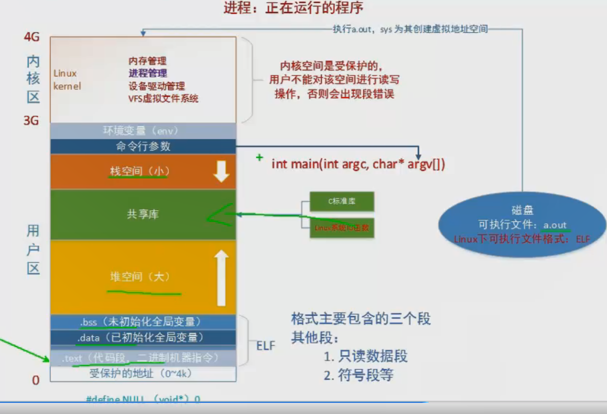
The picture shows a configuration diagram of the virtual address space; There are in the process kernel area management module a process control block (the PCB), is substantially more than four rows o...
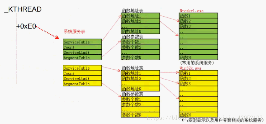
System Descriptor Table and SSDT
The following reference from the water droplet tutorial and https://blog.csdn.net/weixin_42052102/article/details/83118255 System Services Descriptor Table System Services Descriptor Table, that is, t...
More Recommendation
The role of the TSS descriptor table
edit delete The task state descriptor table TSS is used to record the data of the corresponding register when the current process is executing. These data mainly play a role when the process...

GDT and LDT
GDT and LDT LDT belongs to the process, GDT belongs to the system, all processes share a GDT GDT/LDT are both protected modes! reference: Understanding of GDT, GDTR, LDT, LDTR Two pictures to understa...

Global descriptor
The information related to a segment needs 8 bytes to describe, so it is called a segment descriptor. Each segment needs a descriptor. In order to store these descriptors, a space needs to be opened i...
Interprocess communication - redirection, descriptor table
When running a program from the command line, you can use the ">" operator to redirect standard output to a file: Standard input, standard output, standard error are the three default dat...
Table scan descriptor and scan direction
1. The parameters of the table scan function are passed through TableScanDescData. The inner layer of the function stores the scanned records in HeapScanDesc.rs_ctup, and then passes the member conten...