STP configuration of Layer 2 and Layer 3 switches
Configuring STP for Layer 2 Switching
Goal: There may be communication failures caused by line failures in the second-tier network, and the network interruption caused by a line failure can be eliminated through redundant lines.
However, due to the existence of redundant lines, there may be broadcast storms, continuous duplication of the same frames, and instability of the MAC address table.
• Configure Switch1 as the primary root of vlan1 and Switch2 as the secondary root of vlan1
Program:
In order to ensure that there will be no problems such as broadcast storms in a redundant environment, the Spanning Tree (STP) protocol is introduced. Through the spanning tree protocol, a certain port on the redundant line can be placed in the blocking (BLOCKING) state to prevent broadcast storms. When a line fails, the blocked port automatically enters the forwarding (FORWARDING) state to ensure the network The unobstructed.
The network topology is shown below:

Steps:
Step 1: Configure the ports connected to the three switches as trunk ports
tarena-sw1(config)#interface range f0/12 -13
tarena-sw1(config-if-range)#switchport mode trunk
tarena-sw2(config)#interface range f0/12, f0/23
tarena-sw2(config-if-range)#switchport mode trunk
tarena-sw3(config)#interface range f0/13 ,f0/23
tarena-sw3(config-if-range)#switchport mode trunk
Step 2: Adjust the priority and set tarena-sw1 as the root bridge
The only basis for the root bridge is the smallest BID. BID is divided into two parts: priority + MAC address. When comparing BIDs, the priority is compared first, and only the MAC addresses are compared if the priorities are the same.
The priority value range is 0 to 65535, and the default value is 32768. When viewing the priority, even the default value is not 32768, because the priority of the switch adopts the system priority + VLAN number, so the default priority of VLAN1 viewed is 32769 (system priority 32768 + VLAN number 1).
tarena-sw1(config)# spanning-tree vlan 1 priority 28672
tarena-sw1(config)#exit
tarena-sw1#show spanning-tree
VLAN0001
  Spanning tree enabled protocol ieee
  Root ID Priority 28673 //The default priority is 32768
             Address     0060.478B.607B
             This bridge is the root
             Hello Time  2 sec  Max Age 20 sec  Forward Delay 15 sec
  Bridge ID  Priority    28673  (priority 24576 sys-id-ext 1)
             Address     0060.478B.607B
             Hello Time  2 sec  Max Age 20 sec  Forward Delay 15 sec
             Aging Time  20
Interface        Role   Sts   Cost      Prio.Nbr   Type
-----------    ------  --- --------   --------  ----------------------
Fa0/13           Desg    FWD    19        128.13     P2p
Fa0/12           Desg    FWD    19        128.12     P2p
According to the results, the Root ID part refers to the root bridge information, and the Bridge ID part refers to the information of the currently operating switch. If the two are consistent, it means that the currently operating switch is the root bridge.
Layer 3 switching configuration STP
Goal: Configure Switch1 as the secondary root of vlan1 and Switch2 as the secondary root of vlan1.
Configure Switch1 as the secondary root of vlan2, and Switch2 as the secondary root of vlan2
Program:
The network topology as shown in the figure below:

Steps:
Step 1: Configure the ports connected to the four switches as trunk ports, and create vlan2 respectively
SM1(config)#vlan 2
SM1(config)#exit
SM1(config)#interface range fastEthernet 0/1-3
SM1(config-if-range)#switchport trunk encapsulation dot1q
SM1(config-if-range)#switchport mode trunk
SM2(config)#vlan 2
SM2(config)#exit
SM2(config)#interface range fastEthernet 0/1-3
SM2(config-if-range)#switchport trunk encapsulation dot1q
SM2(config-if-range)#switchport mode trunk
Switch1(config)#vlan 2
Switch1(config)#exit
Switch1(config)#interface range fastEthernet 0/1-2
Switch1(config-if-range)#switchport mode trunk
Switch2(config)#vlan 2
Switch2(config)#exit
Switch2(config)#interface range fastEthernet 0/1-2
Switch2(config-if-range)#switchport mode trunk
Step 2: Set SM1 as the secondary root of vlan1's primary root vlan2, and set SM2 as the secondary root of vlan2's primary root vlan1 and check
SM1(config)#spanning-tree vlan 1 root primary
SM1(config)#spanning-tree vlan 2 root secondary
SM1#show spanning-tree
VLAN0001
Spanning tree enabled protocol ieee
Root ID Priority 24577
Address 00D0.972A.43E5
This bridge is the root
Hello Time 2 sec Max Age 20 sec Forward Delay 15 sec
Bridge ID Priority 24577 (priority 24576 sys-id-ext 1)
Address 00D0.972A.43E5
Hello Time 2 sec Max Age 20 sec Forward Delay 15 sec
Aging Time 20
Interface Role Sts Cost Prio.Nbr Type
---------------- ---- --- --------- -------- --------------------------------
Fa0/2 Desg FWD 19 128.2 P2p
Fa0/3 Desg FWD 19 128.3 P2p
Fa0/1 Desg FWD 19 128.1 P2p
VLAN0002
Spanning tree enabled protocol ieee
Root ID Priority 24578
Address 00E0.F9CE.7424
Cost 19
Port 3(FastEthernet0/3)
Hello Time 2 sec Max Age 20 sec Forward Delay 15 sec
Bridge ID Priority 28674 (priority 28672 sys-id-ext 2)
Address 00D0.972A.43E5
Hello Time 2 sec Max Age 20 sec Forward Delay 15 sec
Aging Time 20
Interface Role Sts Cost Prio.Nbr Type
---------------- ---- --- --------- -------- --------------------------------
Fa0/2 Desg FWD 19 128.2 P2p
Fa0/3 Root FWD 19 128.3 P2p
Fa0/1 Desg FWD 19 128.1 P2p
SM2(config)#spanning-tree vlan 1 root secondary
SM2(config)#spanning-tree vlan 2 root primary
SM2#show spanning-tree
VLAN0001
Spanning tree enabled protocol ieee
Root ID Priority 24577
Address 00D0.972A.43E5
Cost 19
Port 3(FastEthernet0/3)
Hello Time 2 sec Max Age 20 sec Forward Delay 15 sec
Bridge ID Priority 28673 (priority 28672 sys-id-ext 1)
Address 00E0.F9CE.7424
Hello Time 2 sec Max Age 20 sec Forward Delay 15 sec
Aging Time 20
Interface Role Sts Cost Prio.Nbr Type
---------------- ---- --- --------- -------- --------------------------------
Fa0/2 Desg FWD 19 128.2 P2p
Fa0/1 Desg FWD 19 128.1 P2p
Fa0/3 Root FWD 19 128.3 P2p
VLAN0002
Spanning tree enabled protocol ieee
Root ID Priority 24578
Address 00E0.F9CE.7424
This bridge is the root
Hello Time 2 sec Max Age 20 sec Forward Delay 15 sec
Bridge ID Priority 24578 (priority 24576 sys-id-ext 2)
Address 00E0.F9CE.7424
Hello Time 2 sec Max Age 20 sec Forward Delay 15 sec
Aging Time 20
Interface Role Sts Cost Prio.Nbr Type
---------------- ---- --- --------- -------- --------------------------------
Fa0/2 Desg FWD 19 128.2 P2p
Fa0/1 Desg FWD 19 128.1 P2p
Fa0/3 Desg FWD 19 128.3 P2p
Intelligent Recommendation

Configuration examples and principles of Layer 3 switches
Overview and advantages of VLAN The Chinese name of VLAN (Virtual Local Area Network) is "Virtual Local Area Network". A virtual local area network (VLAN) is a group of logical devices and u...
Basic configuration of ZTE Layer 3 switches
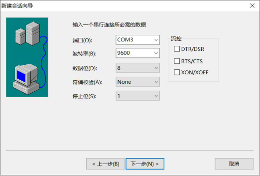
1. The purpose of the experiment 1. Master the login and basic configuration methods of ZTE's three-layer switch 3950 2. Experimental content 1. Use the RS232 serial port to log in to ZTE's Layer 3 sw...
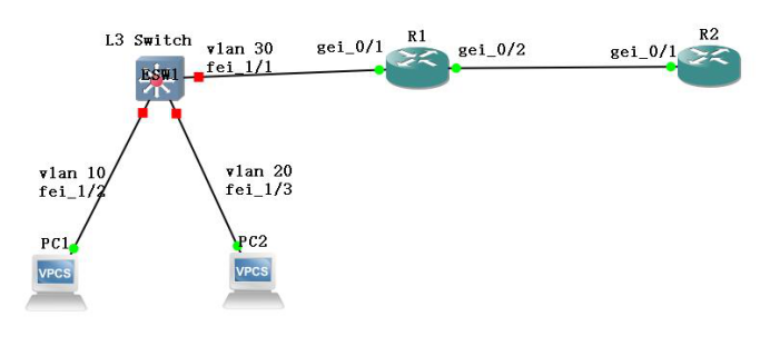
Configuration of VLAN routing for Layer 3 switches
1. The purpose of the experiment Master the VLAN routing configuration method and result verification of the three-layer switch VLAN routing. 2. Experimental content Complete the configuration and res...
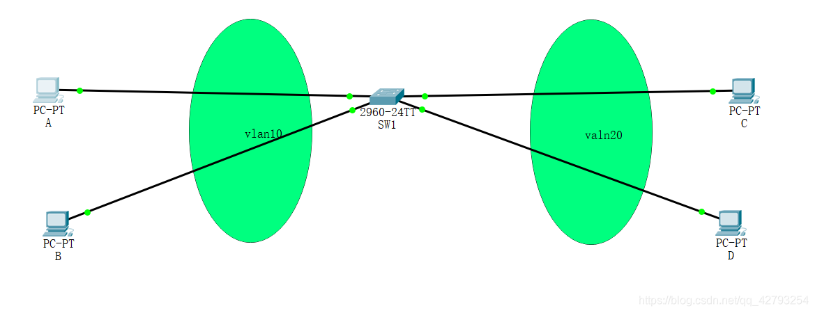
VLAN configuration experiment for Layer 2 switches
VLAN configuration experiment for Layer 2 switches As shown in the figure: port fa0/1 and port fa0/2 of switch SW1 belong to the access port of vlan 10; fa0/1 connects to PC A, and fa0/2 connects to P...
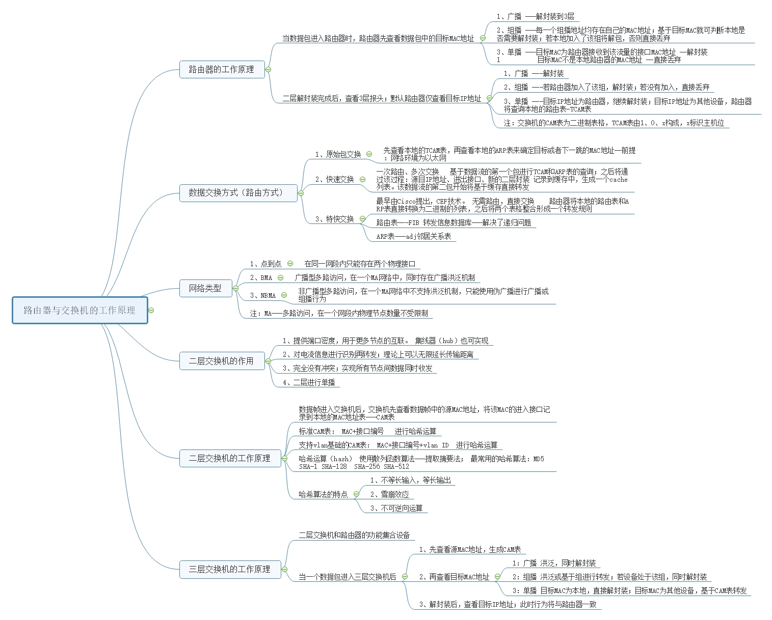
Working principle of routers, Layer 2 and Layer 3 switches
How the router works Router (Layer 3 equipment) When the packet enters the router, the router first checks the target MAC address in the packet; 1、broadcast -Decapsulation to 3 layers &nbs...
More Recommendation

VLAN and Layer 3 switches
Article Directory Overview and advantages of VLAN Trunk overview Layer 3 switching technology Three-layer exchange experiment Overview and advantages of VLAN VLAN is an emerging data exchange technolo...
Configuration of three-layer switches
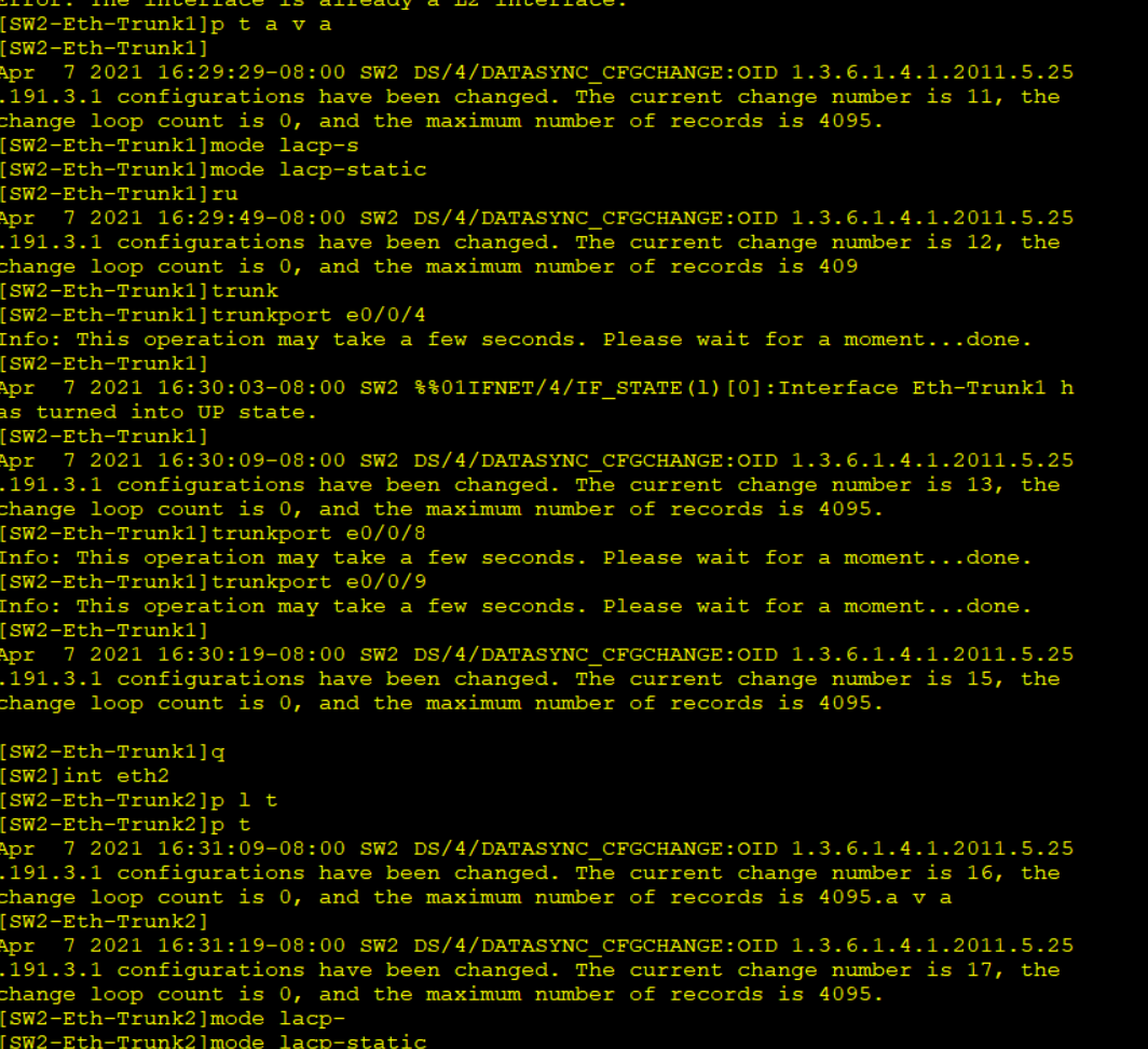
First, experiments: all net interoperability 1. Make LACP link aggregation between Layers Switches 2.R1 and R4 have a link to do floating routing Configure SW1 Configure SW2 Configure SW3 ** ** `` Con...
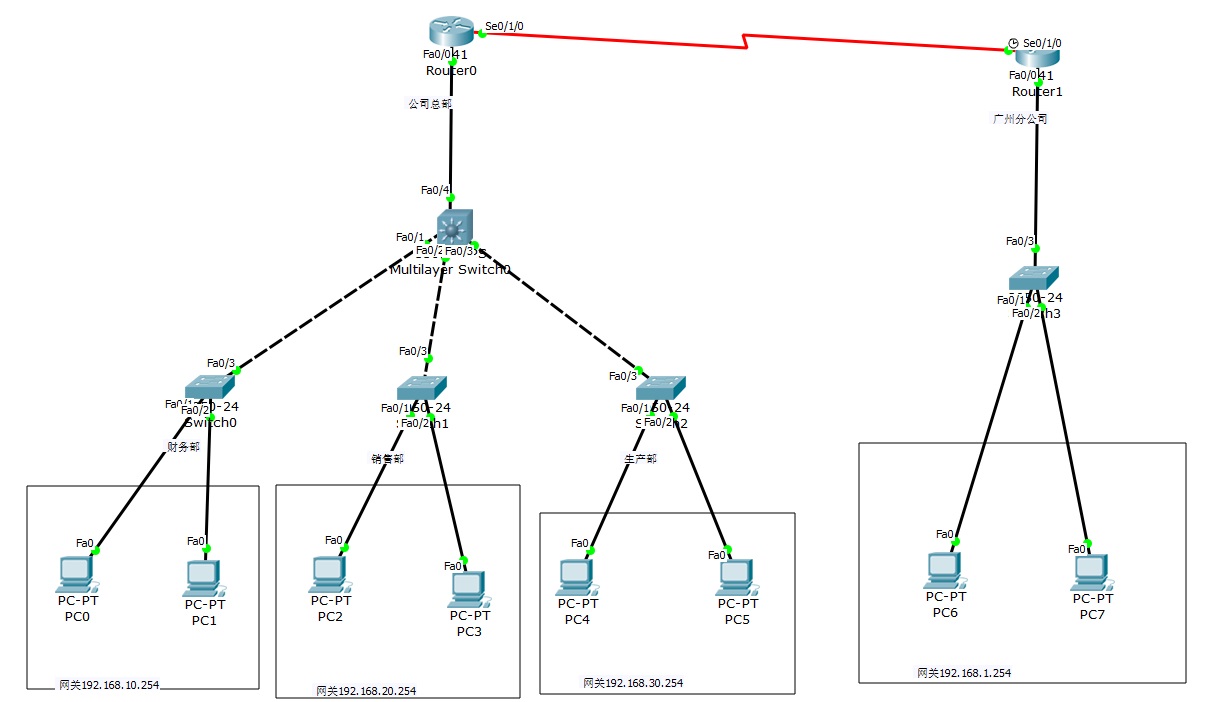
2 routers, 4 Layer 2 switches, and 1 Layer 3 switches to realize network interconnection
The router on the left represents the inside, the router on the right represents the outsideAfter setting up, everything can be pinged Finance Department VLAN10, 192.168.10.1/2 (two PCs) Sales departm...

VLAN division of Layer 3 switches
Configuration on SW1 Configuration on SW2 SW3Configuration on SW1>en &n...
Common commands for Layer 3 switches
Cisco Layer 3 Switch 1. Common command mode 2. Mode conversion command 3. Common commands Common Commands of H3C Switch 1. View port status under Linux 2. The H3C switch displays the current configura...