AXI Basics Part 3-Using AXI VIP to Simulate AXI4-Lite Master Interface
tags: AXI
This technical article comes from the "Xilinx Product Design and Function Debugging Skills" section of Xilinx Chinese Forum. For more information, please visit https://forums.xilinx.com/cn
This reprint has been authorized. If you need to reprint, please indicate the source author and Xilinx forum link and send an email to [email protected]. Without permission from Xilinx and the copyright owner, it is prohibited For commercial purposes
In this new blog post, let’s talk about how to add AXI VIP to the Vivado project and simulate the AXI4-Lite interface. Later, we will explain the signals used for AXI4-Lite transmission transactions in the simulation waveform window.
Use AXI VIP as AXI4-Lite master interface (tutorial)
1. Download the design file (attached to this article)

 2. Open Vivado 2019.2.

 3. In the Tcl console, use cd  Command to enter the unzipped directory (cd AXI_Basics_3)

 4. In Tcl, use source  Command to execute tcl script(source./create_proj.tcl)
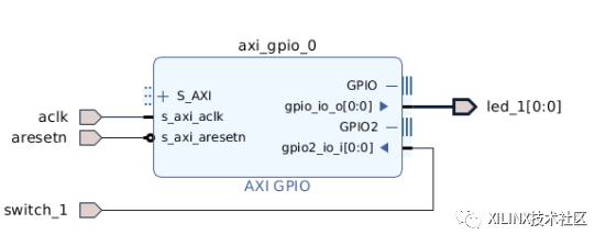
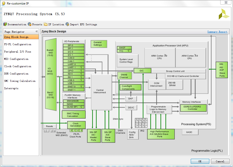
This will create a Vivado project with a Block Design containing the AXI GPIO IP. Channel 1 of this AXI GPIO IP is used as an external output interface to simulate the connection to the onboard LED. We will try to switch this LED through AXI4-Lite transmission transaction; meanwhile, channel 2 of this IP is used as an external input interface for To simulate the connection to the onboard switch, we will try to read the state of this switch.
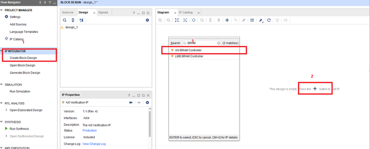
5. Add AXI Verification IP (AXI VIP) to the design.
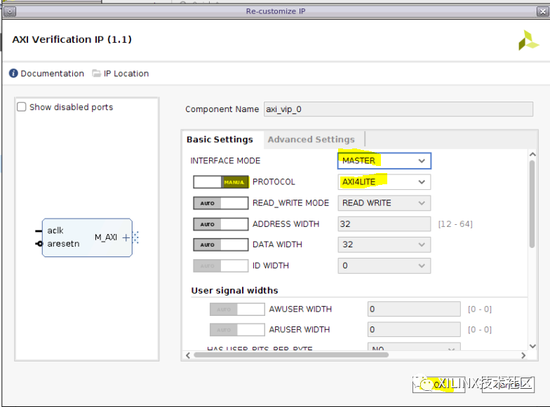
6. Double-click AXI VIP to open its configuration GUI and modify the following parameters:
1、Interface mode:MASTER

2、 Protocol (MANUAL):AXI4LITE
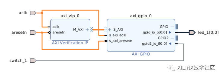
7. Connect the AXI4-Lite master interface (M_AXI) of AXI VIP to the AXI4-Lite slave interface (S_AXI) of AXI GPIO IP, and connect the aclk and aresetn ports of AXI VIP to the block Design input
8. Open the "Address Editor" tab ("Window> Address Editor") and click the "Auto Assign Address" icon
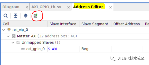
- Confirm that this address is set to 0x4000_0000
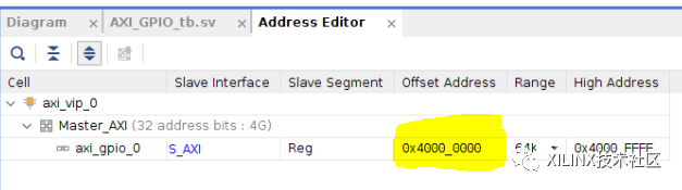
Note: The upper part of the address here is irrelevant, because of the S_AXI interface of AXI GPIO, only 9 address bits are connected to AXI VIP
Click the "Verify Block Design" icon. Make sure that there are no serious warnings or errors. Then save the block design. Now, we need to update the test incentive file to declare instantiation and control of AXI VIP. To this end, we will follow the contents of the "Practical Coding Guidelines and Examples" section in (PG267 (October 30, 2019 v1.1)).

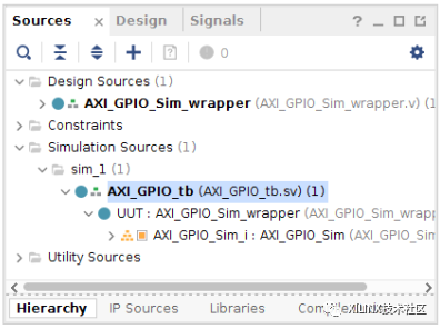
- Open the test stimulus file AXI_GPIO_tb.sv from the "Sources" window
The test stimulus file already contains the control logic of some signals (for example, clock and reset), and contains the process of outputting the LED status to the console.
always @(posedge led_1)

begin

     $display("led 1 ON");

end

always @(negedge led_1)

begin

     $display("led 1 OFF");

end
The first step mentioned in "Practical Coding Guidelines and Examples" is to create a module in the SystemVerilog test stimulus. This operation is completed in this test stimulus file.
The second step is to import 2 required packages: axi_vip_pkg and <component_name>_pkg.
Note: Please use the following Tcl command to find the <component_name> of the VIP instance and the output corresponding to the AXI VIP instance.
The attached test stimulus assumes the AXI component name is design_1_axi_vip_0_0 (the default name of the first AXI VIP added to BD)
get_ips *vip*
12. Add the following line near line 58
//Step 2 - Import two required packages: axi_vip_pkg and <component_name>_pkg.

import axi_vip_pkg::*;

import AXI_GPIO_Sim_axi_vip_0_0_pkg::*;
The third step is to declare the agent of the VIP main interface
13. Add the following line near line 102
// Step 3 - Declare the agent for the master VIP

AXI_GPIO_Sim_axi_vip_0_0_mst_t      master_agent;
Steps 4 and 5 are to create a new agent and start it.
14. Add the following line near line 107
// Step 4 - Create a new agent

master_agent = new("master vip agent",UUT.AXI_GPIO_Sim_i.axi_vip_0.inst.IF);


// Step 5 - Start the agent

master_agent.start_master();
Ready to send transmission transaction.
Sending AXI4-Lite transfer transactions is actually very simple.
Just use AXI4LITE_WRITE_BURST(addr,prot,data,resp) API to perform write transfer transaction,
Use AXI4LITE_READ_BURST(addr,prot,data,resp) API to execute read transfer transaction.
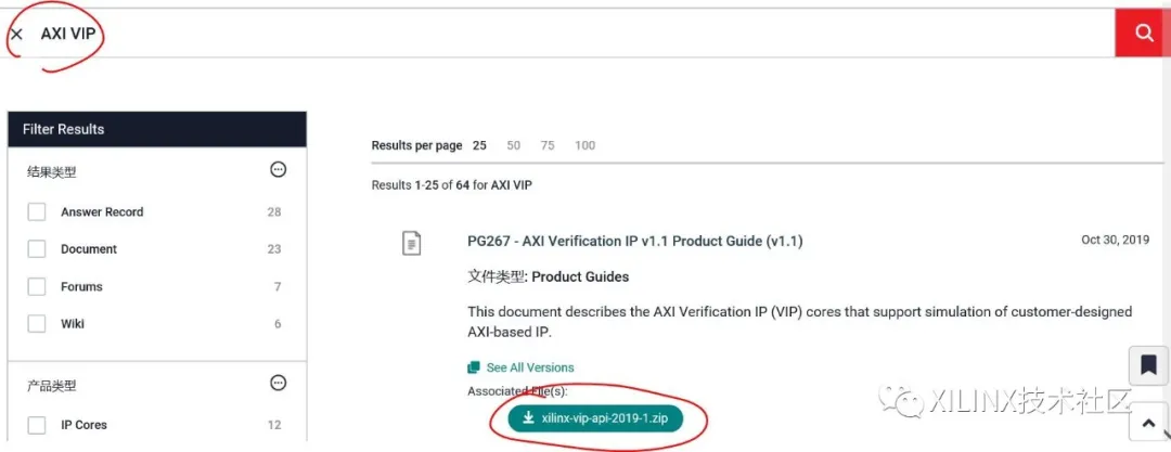
Note: All APIs of AXI VIP are recorded in the zip file, which can be downloaded from china.xilinx.com.
(The download method is as follows: Scan the code to enter Xilinx official website/technical support,
Search for "AXI VIP" to find the ZIP file package or enter the URL, enter "AXI VIP" in the search box
https://china.xilinx.com/support.html#documentation

In this tutorial, we will try to switch LED_1 connected to AXI GPIO channel 1 and read the state of SWITCH_1 connected to AXI GPIO channel 2.
By looking at the register map of the AXI GPIO IP (Table 2-4 of (PG144)), we can see that we must perform a write operation at address 0x0 and a read operation at address 0x8:

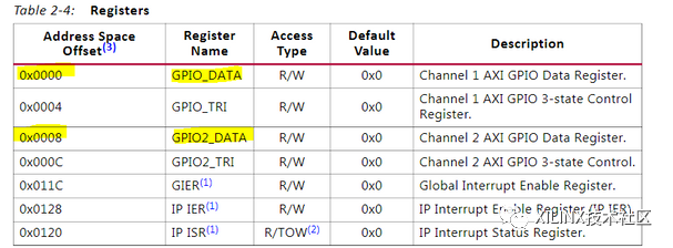
We will start with the write operation and try to switch the state of LED_1.
15. Add the following code to write 0x1 to the AXI GPIO register 0x0, which should turn on this LED
//Send 0x1 to the AXI GPIO Data register 1

#500ns

addr = 0;

data = 1;

master_agent.AXI4LITE_WRITE_BURST(base_addr + addr,0,data,resp);
16. Add the following code to write 0x0 to the AXI GPIO register 0x0, which should turn off this LED
//Send 0x0 to the AXI GPIO Data register 1

#200ns

addr = 0;

data = 0;

master_agent.AXI4LITE_WRITE_BURST(base_addr + addr,0,data,resp);
In the next step, we will read every change in the switch position and display the switch status to the console.
17. Add the following code corresponding to the read transfer transaction:
// Switch in OFF position

switch_1 = 0;

// Read the AXI GPIO Data register 2

#200ns

addr = 8;

master_agent.AXI4LITE_READ_BURST(base_addr + addr,0,data,resp);

switch_state = data&1'h1;

if(switch_state == 0)

    $display("switch 1 OFF");

else

    $display("switch 1 ON");


// Switch in ON position

switch_1 = 1;

// Read the AXI GPIO Data register 2

#200ns

addr = 8;

master_agent.AXI4LITE_READ_BURST(base_addr + addr,0,data,resp);

switch_state = data&1'h1;

if(switch_state == 0)

    $display("switch 1 OFF");

else

    $display("switch 1 ON");
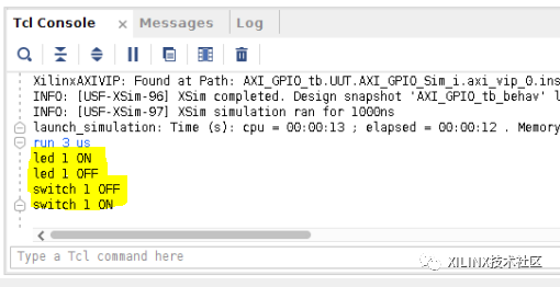
18. Start the simulation and run it for 3us. In the Tcl console, you should be able to see the LED on and off, and see the switch status
Now, we can analyze the transmission transaction on the AXI4-Lite interface
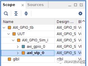
19. In the "Scope" window, select axi_vip_0 under "AXI_GPIO_tb> UUT >AXI_GPIO_Sim_i"
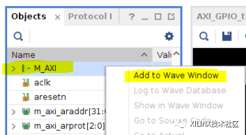
20. In the "Objects" window, right-click the M_AXI protocol instance, and then click "Add to Wave Window"
21. Restart the simulation and run 3us
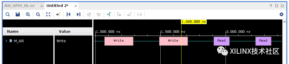
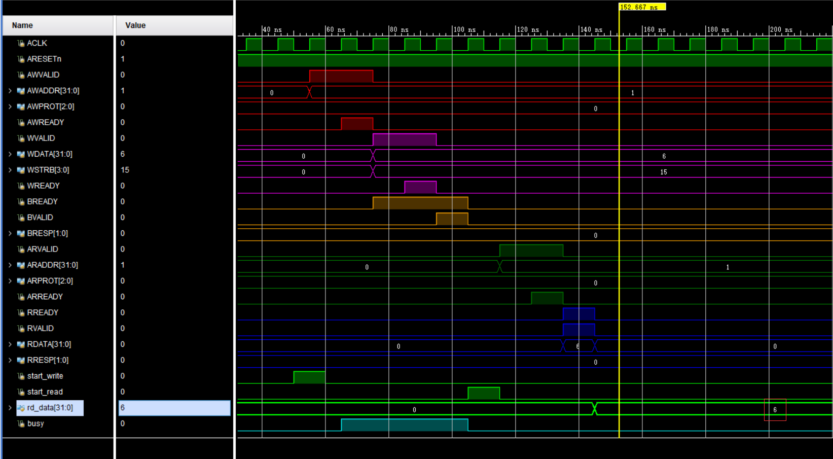
In this way, 4 transfer transactions will be visible on the AXI4-Lite interface: 2 write transfer transactions followed by 2 read transfer transactions
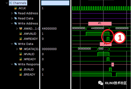
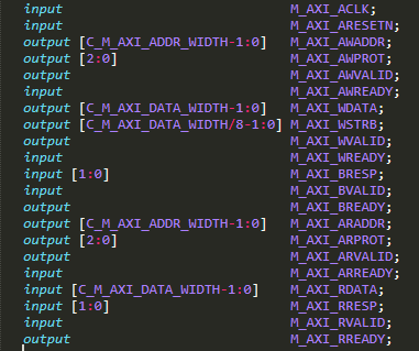
22. Expand the M_AXI protocol instance to view each channel
So you can see the various steps in the write transfer transaction. First, when the READY and VALID signals are both high on the write address channel (AWREADY and AWVALID), the address is transferred from the master interface to the slave interface
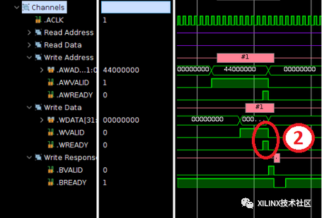
Subsequently, when the READY and VALID signals are both high on the write channel (WREADY and WVALID), the data is transferred from the master interface to the slave interface.
Note: Only one data is transmitted for each address, because burst reading and writing are not supported on the AXI4-Lite interface.
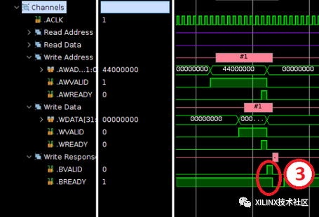
Finally, when the slave interface sends a write response on the write response channel (to indicate whether the write operation is successful), the write transfer transaction is completed. When the READY and VALID signals are both high (BREADY and BVALID) on the write response channel, the response is transmitted from the slave interface to the master interface
For read transfer transactions, this analysis can also be performed. First, when the READY and VALID signals are both in the high position (ARREADY and ARVALID) on the read address channel, the address is transferred from the master interface to the slave interface
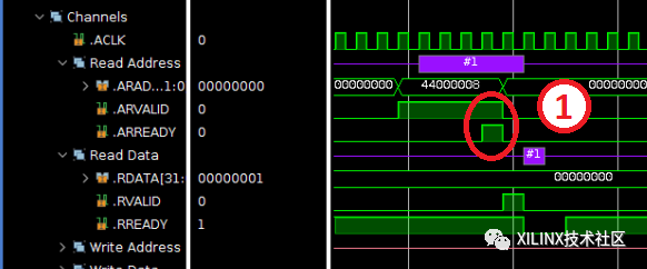
Subsequently, when the READY and VALID signals are both high on the read channel (RREADY and RVALID), the data is transferred from the slave interface to the master interface.
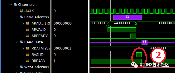
Note: During the execution of a read transfer transaction, the slave interface will also send a read response to indicate whether the read operation is successful.
This response will be sent simultaneously with the data on the read channel.
Intelligent Recommendation
AXI4 (AXI-FULL) bus detail
AXI4 (AXI-FULL) bus detail 1.1 What is AXI 1.1.1 Zynq three AXI bus 1.1.2 AXI's three interfaces 1.1.3 AXI protocol 1.1.3.1 AXI handshake agreement 1.1.3.2 burst reading 1.2 AXI pin description 1.3 Re...
[UVM][AXI][VIP]
First, in the VIP development or application, there will often be a situation where the response queue overflows, and the depth of the response queue should be 8 by default. So how to set it up? Set t...
Simple use of AXI VIP
Article catalog Base use Architecture Official Testbench Example Testbench's considerations Small case Example of example step Generate AXI VIP Add a test file Base use Architecture The AXI VIP uses s...
AXI
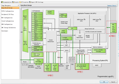
There are 9 AXI interfaces in ZYNQ, which are mainly used for the interconnection of PS and PL, including the following three types: . AXI_ACP interface is an interface defined under the ARM multi-cor...
Interface to a simple handshake interface to read axi lite example BRAM
First, open source axi_master borrow module, first of all I use VHDL tool to XHDL turned into Verilog, and package it became IP, called axi_lite_master_vlog_v1_0. A user-side handshake interfaces as f...
More Recommendation

Take you to quickly get started with AXI4 bus-AXI4-LITE chapter (3) ---- Xilinx Axi4-Lite interface IP source simulation analysis (MASTER interface)
In front existTake you to quickly get started with AXI4 bus-AXI4-LITE chapter (2) ---- Xilinx Axi4-Lite interface IP source simulation analysis (SLAVE interface)In China, we have analyzed the code of ...
FPGA from entry to master (extra 1)-the use of AXI VIP
EDA software used: VIVADO2018.3 FPGA model: xc7a35tcsg325-2 Note: to understand some concepts in this article may require a little systemverilog basis In the previous section, I probably...

ZYNQ-- from entry to departure --AXI bus interface analysis (LITE)
There are in ZYNQ supports three AXI bus, offers three AXI interfaces, of course, are used in the AXI protocol. Three of the AXI bus are: AXI4: (. For high-performance memory-mapped requirements) main...

[Tips] Using XDMA to implement PCIE mapping AXI-Lite to configure VDMA
Many ips provided by Xilinx, such as VDMA, OSD, Mixer, TPG, etc., need to be configured before use. The configuration interface is often AXI-Lite interface. Under normal circumstances, we usually writ...
AXI Lite Protocol Learning and Simulation
The AXI4-Lite Bus Agreement includes 21 signal lines. Each channel has its own two-way handshake mechanism signal line XXValid and XXReady, with respect to the two-way handshake mechanism, you can see...