Comprehensive experiments based on routers, switches, vlan, ARP, Layer 3 switches, HSRP, ACL, NAT
tags: Qianfeng Network Security Video Notes The internet router switch
Through the previous learning of routers, switches, vlan, ARP, three-layer switches, HSRP, ACL, NAT, and dynamic routing, I have a further understanding and learning of network construction and planning. Today I will combine the knowledge I have learned to complete the construction of this large-scale network!
If you have any questions about the above knowledge points, please refer to my previous blog:
[Network Security Learning Chapter 13]: Learning the data link layer and switches (Qianfeng Network Security Video Notes 13 day)
[Network Security Study 14]: ARP protocol, ARP spoofing and attacks (Qianfeng Network Security Video Notes 14 day)
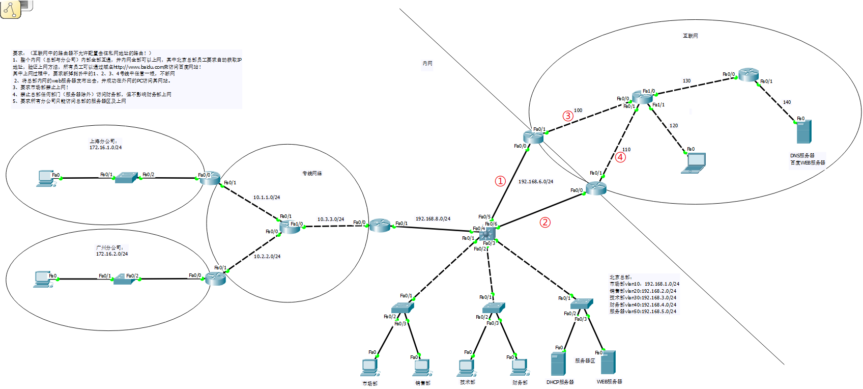
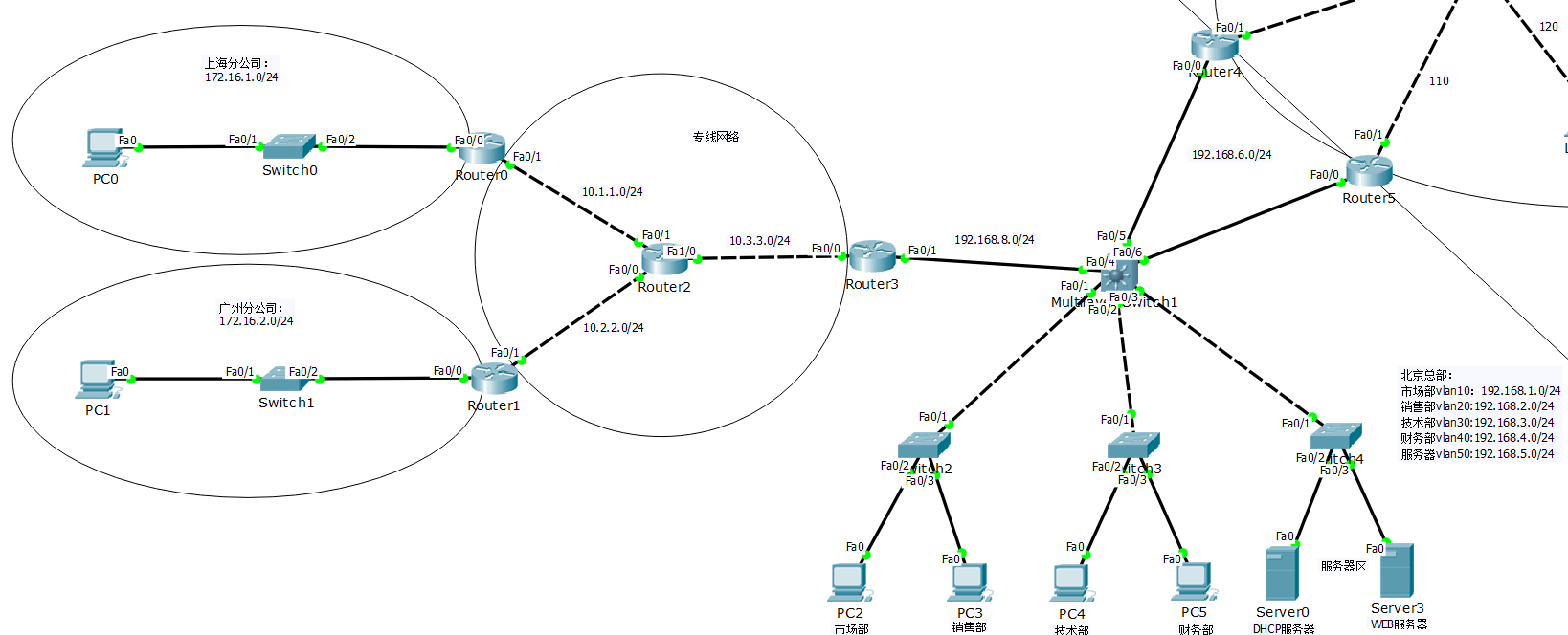
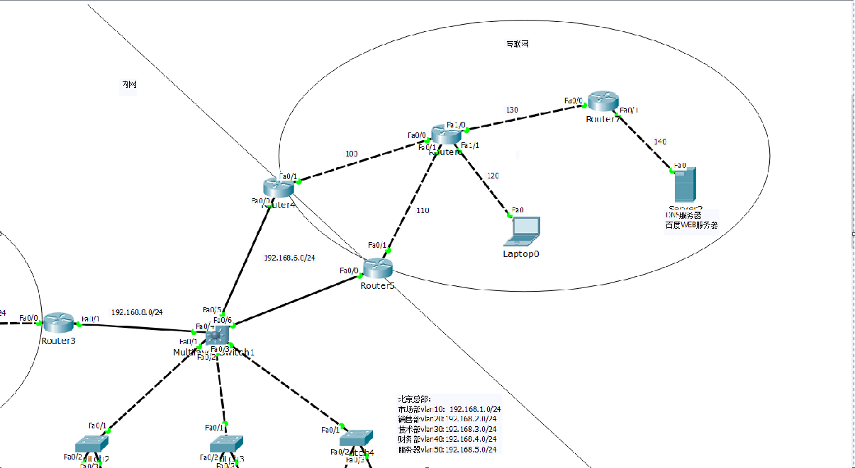
Experimental topology diagram:
Claim:
(The router in the Internet does not allow you to configure the route to the private network address!)
1. The entire intranet (headquarters and branch offices) is interconnected internally, and all intranets can access the Internet, among which the employees of Beijing headquarters require automatic IP
Address, verify the Internet method, all employees can visit Baidu website through the domain name http://www.baidu.com!
In the process of surfing the Internet, it is required to disconnect any one of the 1, 2, 3, and 4 lines in the topology to keep the Internet
2. Publish the web server of the headquarters' intranet and successfully access its website on the PC of the extranet.
3. Request the marketing department to ban Internet access!
4. Any department of the headquarters (except the server) is prohibited from accessing the Finance Department, but it does not affect the Internet of the Finance Department
5. All branches are required to only access the server area of the headquarters and surf the Internet
Okay, let's configure this large guy next!
1. Complete the network configuration of the branch:
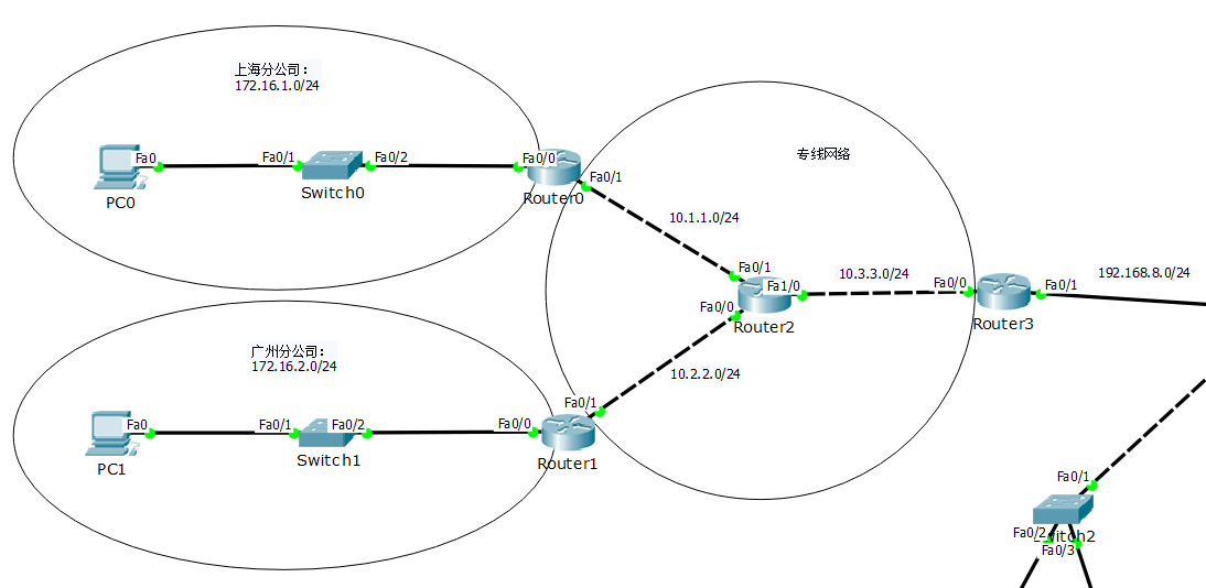
Router0:
en
conf t
int f0/0
    ip add 172.16.1.254 255.255.255.0
    no sh
    ex
int f0/1
    ip add 10.1.1.1 255.255.255.0
    no sh
    ex
ip route 0.0.0.0 0.0.0.0 10.1.1.2
Router1:
en
conf t
int f0/0
    ip add 172.16.2.254 255.255.255.0
    no sh
    ex
int f0/1
    ip add 10.2.2.1 255.255.255.0
    no sh
    ex
ip route 0.0.0.0 0.0.0.0 10.2.2.2
Router2:
en
conf t
int f0/0
    ip add 10.2.2.2 255.255.255.0
    no sh
    ex
int f0/1
    ip add 10.1.1.2 255.255.255.0
    no sh
    ex
int f1/0
    ip add 10.3.3.1 255.255.255.0
    no sh
    ex
ip route 0.0.0.0 0.0.0.0 10.3.3.2
ip route 172.16.1.0 255.255.255.0 10.1.1.1
ip route 172.16.2.0 255.255.255.0 10.2.2.1
Router3:
en
conf t
int f0/0
ip add 10.3.3.2 255.255.255.0
no sh
ex
int f0/1
ip add 192.168.8.1 255.255.255.0
no sh
ex
ip route 0.0.0.0 0.0.0.0 192.168.8.2
ip route 10.1.1.0 255.255.255.0 10.3.3.1
ip route 10.2.2.0 255.255.255.0 10.3.3.1
ip route 172.16.1.0 255.255.255.0 10.3.3.1
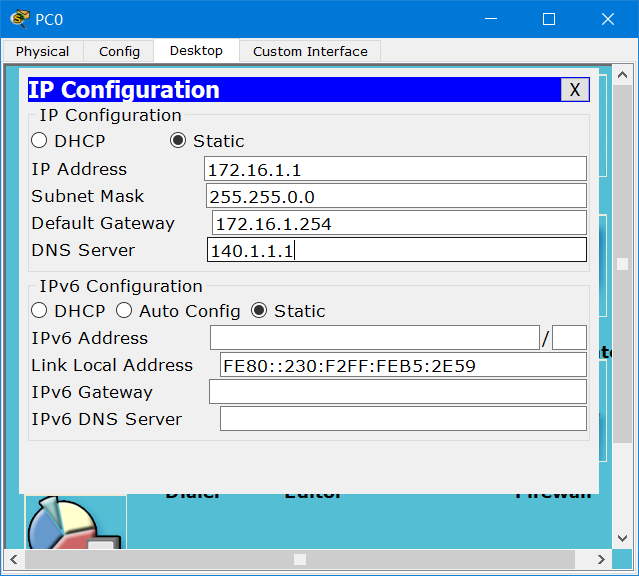
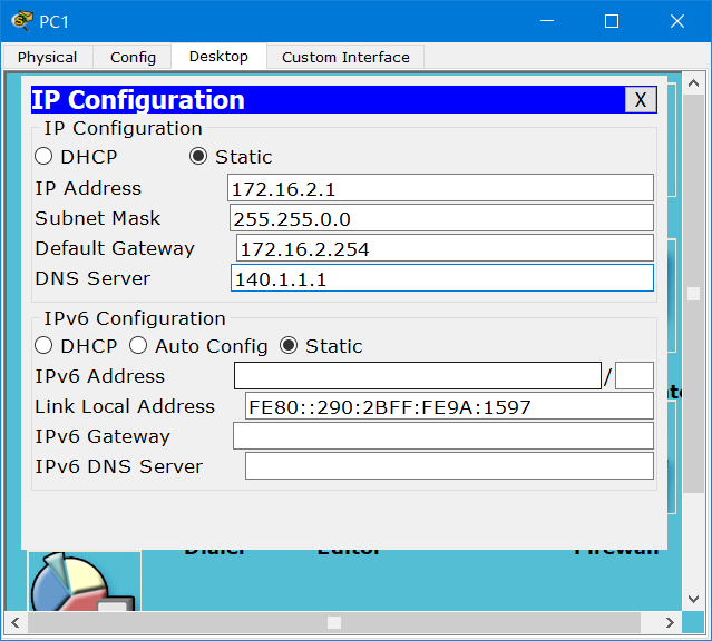
ip route 172.16.2.0 255.255.255.0 10.3.3.1Configure IP for PC0 and PC1
DNS, point to the DNS server of the external network, so that the web server of the external network can be accessed through the domain name in the future
Test network connectivity:

The whole network has been connected.
2. Realize the internal network connection of the head office and the network connection with the branch company
1)trunk
Switch2:
en
conf t
int f0/1
    sw m t
Switch3:
en
conf t
int f0/1
    sw m t
Switch4:
en
conf t
int f0/1
    sw m t
Layer 3 switch:
en
conf t
int range f0/1-3
    sw tr en dot
    sw m t
    ex

int range f0/5-6
    sw tr en dot
    sw m t
    ex
2) vtp and vlan
Layer 3 switch
en
conf t
vtp domain test
vlan 10
vlan 20
vlan 30
vlan 40
vlan 50
    ex

int f0/5
    sw ac vlan 60
int f0/6
    sw ac vlan 60
    ex

int vlan 10
    ip add 192.168.1.254 255.255.255.0
    no sh
int vlan 20
    ip add 192.168.2.254 255.255.255.0
    no sh
int vlan 30
    ip add 192.168.3.254 255.255.255.0
    no sh
int vlan 40
    ip add 192.168.4.254 255.255.255.0
    no sh
int vlan 50
    ip add 192.168.5.254 255.255.255.0
    no sh
int vlan 60
    ip add 192.168.6.254 255.255.255.0
    no sh
    ex
Switch2:
int f0/2
    sw ac vlan 10
    ex
int f0/3
    sw ac vlan 20
    ex
Switch3:
int f0/2
    sw ac vlan 30
    ex
int f0/3
    sw ac vlan 40
    ex
Switch4:
int f0/2
    sw ac vlan 50
    ex
int f0/3
    sw ac vlan 50
    ex
3) Configure routing
Layer 3 switch
en
conf t
ip routing
int f0/4
    no sw
    ip add 192.168.8.2 255.255.255.0
    no sh
    ex

ip route 172.16.1.0 255.255.255.0 192.168.8.1
ip route 172.16.2.0 255.255.255.0 192.168.8.1
ip route 10.1.1.0 255.255.255.0 192.168.8.1
ip route 10.2.2.0 255.255.255.0 192.168.8.1
ip route 10.3.3.0 255.255.255.0 192.168.8.1
4) Configure the DHCP server
Layer 3 switch
int vlan 10
    ip helper 192.168.5.1
int vlan 20
    ip helper 192.168.5.1
int vlan 30
    ip helper 192.168.5.1
int vlan 40
    ip helper 192.168.5.1
Serrver0:
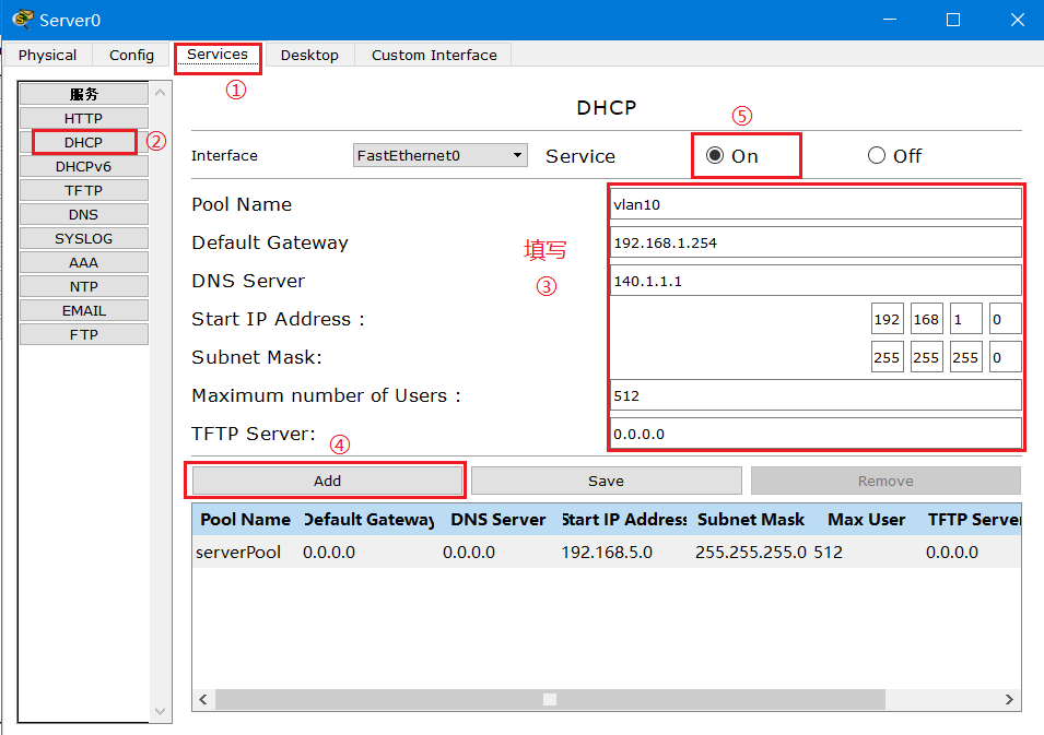
After the 4 van network segments are configured, click to start the service.
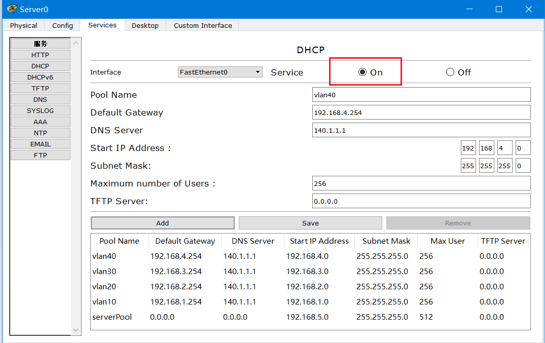
Okay, now we turn on the PC and we can get the IP automatically
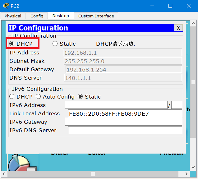
After obtaining the IP, the network segment of the whole company can communicate with each other
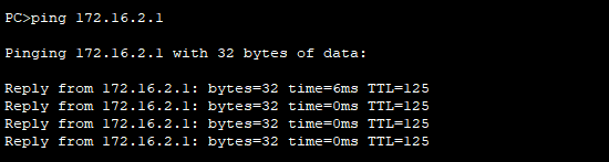
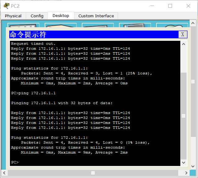
Test: Use PC2 to ping the PC of the Shanghai branch, the test is successful!
3) Interoperability between internal and external networks
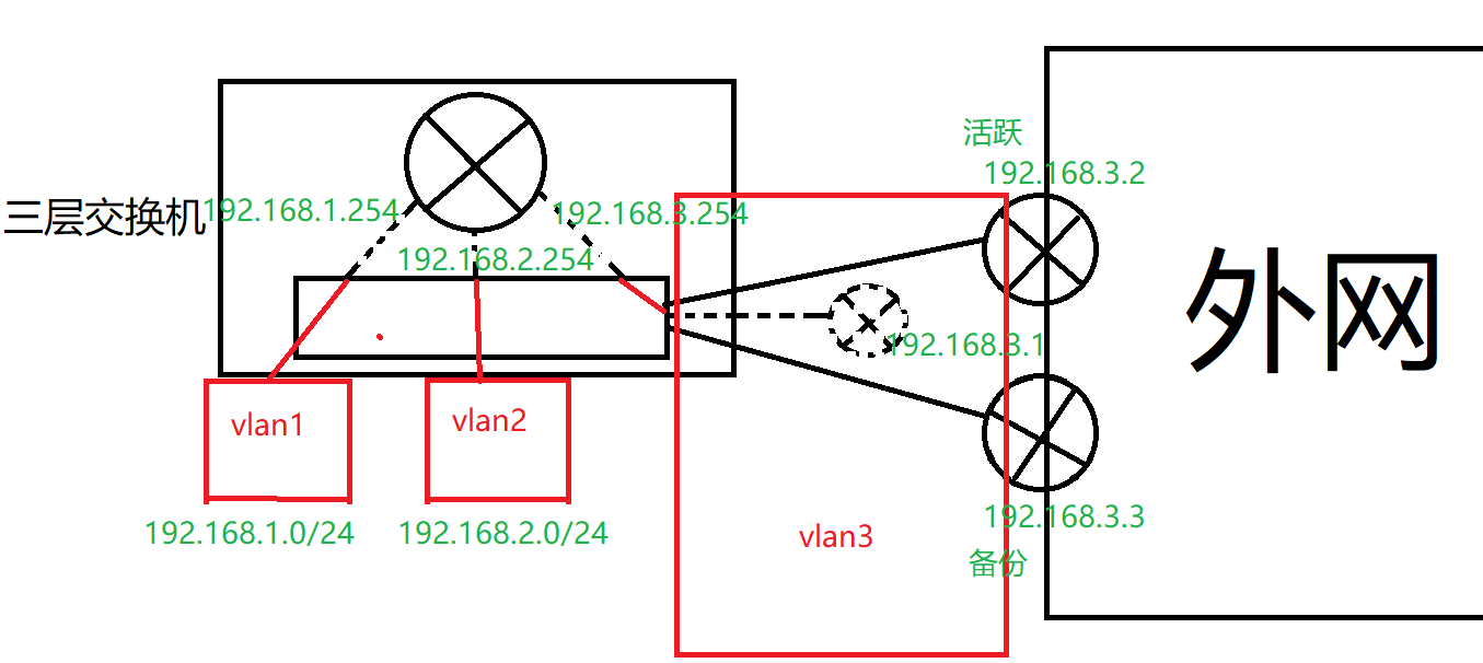
1) Configure HSRP (hot backup)
Router4:
en
conf t
int f0/0
    ip add 192.168.6.252 255.255.255.0
    no sh
    standby 1 ip 192.168.6.250
    standby 1 pri 200
    standby 1 pree
    standby 1 tra f0/1
    ex
int f0/1
    ip add 100.1.1.1 255.255.255.0
    no sh
    ex

ip route 192.168.1.0 255.255.255.0 192.168.6.254
ip route 192.168.2.0 255.255.255.0 192.168.6.254
ip route 192.168.3.0 255.255.255.0 192.168.6.254
ip route 192.168.4.0 255.255.255.0 192.168.6.254
ip route 192.168.5.0 255.255.255.0 192.168.6.254
ip route 172.16.1.0 255.255.255.0 192.168.6.254
ip route 172.16.2.0 255.255.255.0 192.168.6.254
Router5:
en
conf t
int f0/0
    ip add 192.168.6.253 255.255.255.0
    no sh
    standby 1 ip 192.168.6.250
    standby 1 pri 195
    standby 1 pree
    standby 1 tr f0/1
    ex
int f0/1
    ip add 110.1.1.1 255.255.255.0
    no sh
    ex

ip route 192.168.1.0 255.255.255.0 192.168.6.254
ip route 192.168.2.0 255.255.255.0 192.168.6.254
ip route 192.168.3.0 255.255.255.0 192.168.6.254
ip route 192.168.4.0 255.255.255.0 192.168.6.254
ip route 192.168.5.0 255.255.255.0 192.168.6.254
ip route 172.16.1.0 255.255.255.0 192.168.6.254
ip route 172.16.2.0 255.255.255.0 192.168.6.254
2) Configure routing
Router6:
en
conf t
int f0/0
    ip add 100.1.1.2 255.255.255.0
    no sh
int f0/1
    ip add 110.1.1.2 255.255.255.0
    no sh
int f01/0
    ip add 130.1.1.1 255.255.255.0
    no sh
int f1/1
    ip add 120.1.1.254 255.255.255.0
    no sh
ip route 140.1.1.0 255.255.255.0 130.1.1.2
Router7:
en
conf t
int f0/0
    ip add 130.1.1.2 255.255.255.0
    no sh
int f0/1
    ip add 140.1.1.254 255.255.255.0
    no sh
ip route 0.0.0.0 0.0.0.0 130.1.1.1
Laptop0:
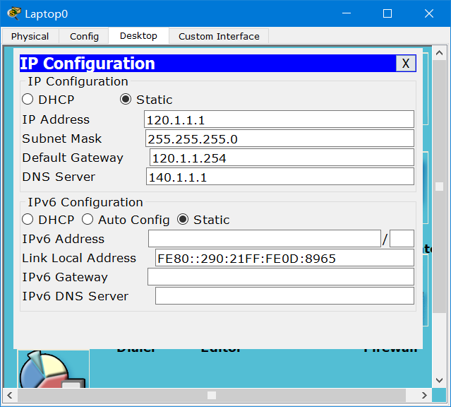
5)NAT
Router4:
int f0/0
    ip nat inside
    ex
int f0/1
    ip nat outside
    ex

acc 1 permit 192.168.0.0 0.0.255.255
acc 1 permit 172.16.1.0 0.255.255.255
acc 1 permit 172.16.2.0 0.255.255.255

ip nat inside sou list 1 int f0/1 overload
Router5:
int f0/0
    ip nat inside
    ex
int f0/1
    ip nat outside
    ex

acc 1 permit 192.168.0.0 0.0.255.255
acc 1 permit 172.16.1.0 0.255.255.255
acc 1 permit 172.16.2.0 0.255.255.255

ip nat inside sou list 1 int f0/1 overload
4) Configure DNS server
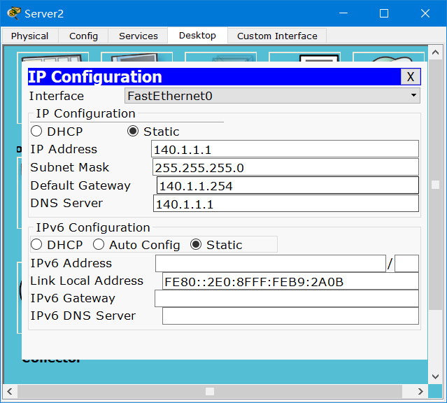
One address is the IP address of Baidu web server, and the other is the company's web server address.

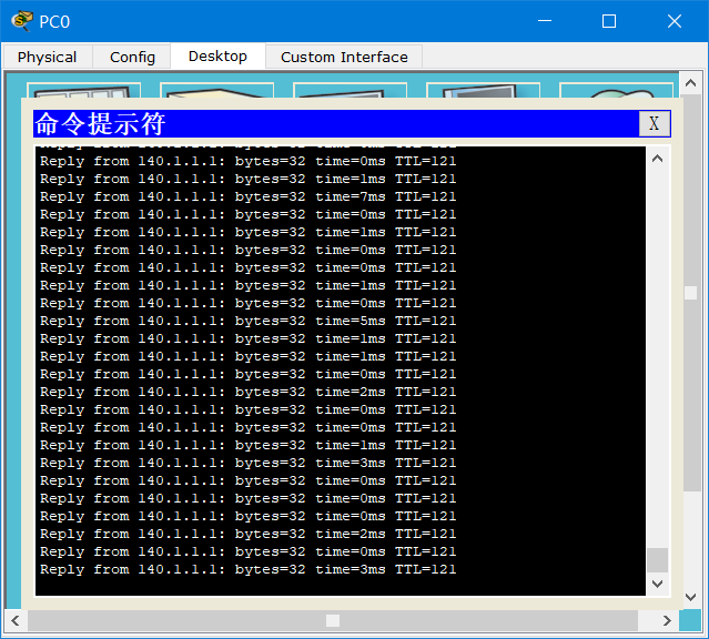
test:
Use the branch PC to ping 140.1.1.1
ping -t 140.1.1.1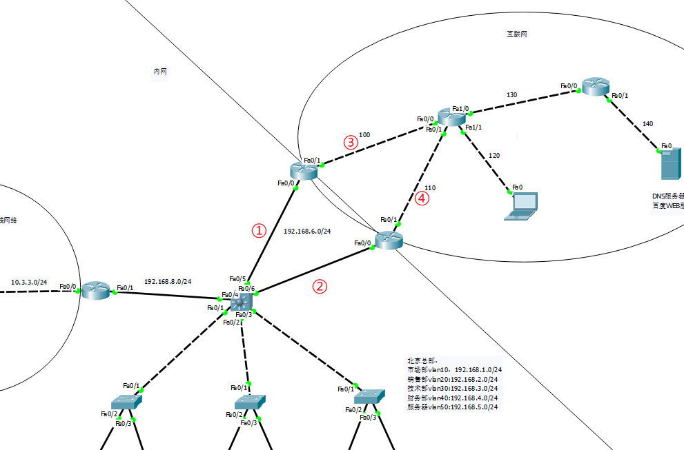
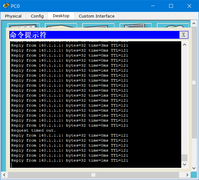
Disconnect ①, network connection:
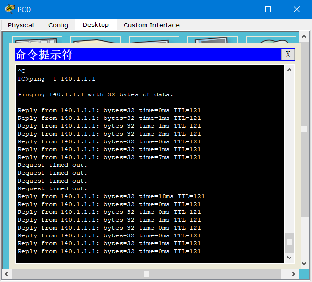
Disconnect ②, network connection:

Disconnect ③, network connection:
Disconnect ④, network connection:
4. Control the network through ACL packet filtering
Intelligent Recommendation
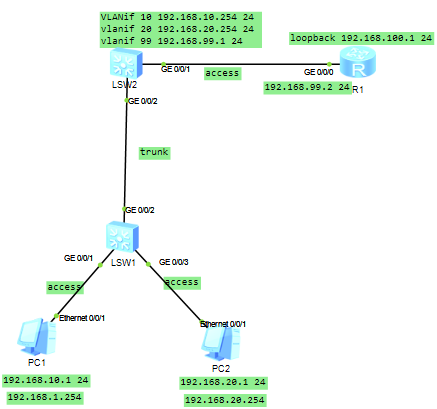
Layer 3 switches implement VLAN interconnection
1. The VLANIF interface is based on the network layer and can be configured with an IP address. With the help of the VLANIF interface, the layer 3 switch can realize the route forwarding function. Bef...
Configuration of VLAN routing for Layer 3 switches
1. The purpose of the experiment Master the VLAN routing configuration method and result verification of the three-layer switch VLAN routing. 2. Experimental content Complete the configuration and res...
H3C switches for access restrictions based on advanced ACL - Experiments
[If you have any questions in the experiment, welcome attention to the micro-channel public number "IT backyard" Give me a message, I will find time to answer your question] Article Director...
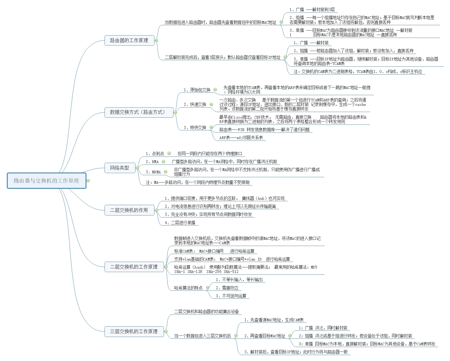
Working principle of routers, Layer 2 and Layer 3 switches
How the router works Router (Layer 3 equipment) When the packet enters the router, the router first checks the target MAC address in the packet; 1、broadcast -Decapsulation to 3 layers &nbs...
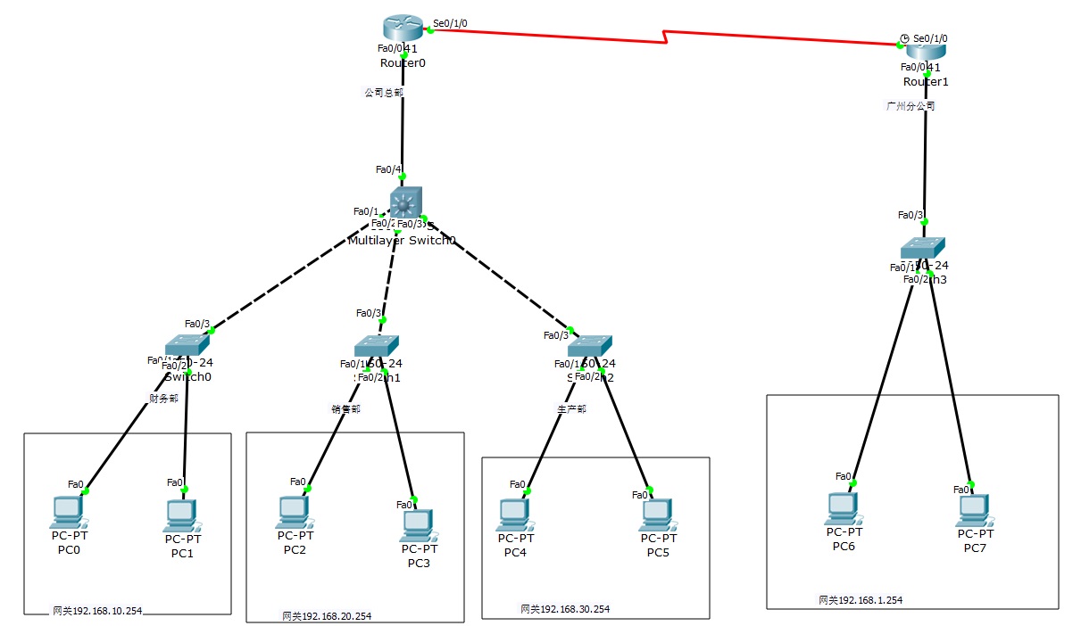
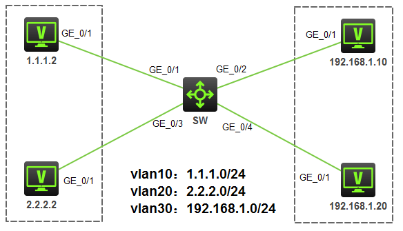
2 routers, 4 Layer 2 switches, and 1 Layer 3 switches to realize network interconnection
The router on the left represents the inside, the router on the right represents the outsideAfter setting up, everything can be pinged Finance Department VLAN10, 192.168.10.1/2 (two PCs) Sales departm...
More Recommendation
Huawei Routing Switching-Links between Layer 3 switches and routers
The method of link connection between switch and router: Method 1: Set vlanif and static route Method 2: Run ospf on the switch and router The topology diagram is as follows: Method one configuration ...

Let you know at a glance-the difference between routers and Layer 3 switches
When the router receives a data packet, it will check the routing table. If there is the same network segment, performLongest mask match, And then forward the data packet to this port, and discard it ...
Routers and switches
The functions of routers and switches are different. The role of the router is to communicate with the outside. The switch provides intranet communication. Not every network needs a router. Compared t...
Switches and routers
2019/07/25 Today, when I re-learned the content of the openstack network part, I wondered about the content of the switch again. In fact, there is nothing in essence, but when I think about the networ...

Netmiko changes the VLAN and ACL of Huawei switches in batches.
First, introduction There are thousands of Huawei switches in the intranet environment, and there is a problem before, but it needs to be changed, but a station change is time-consuming, so the mass o...