Crystal Oscillator Circuit
tags: crystal oscillator
Crystal oscillator circuit and working principle
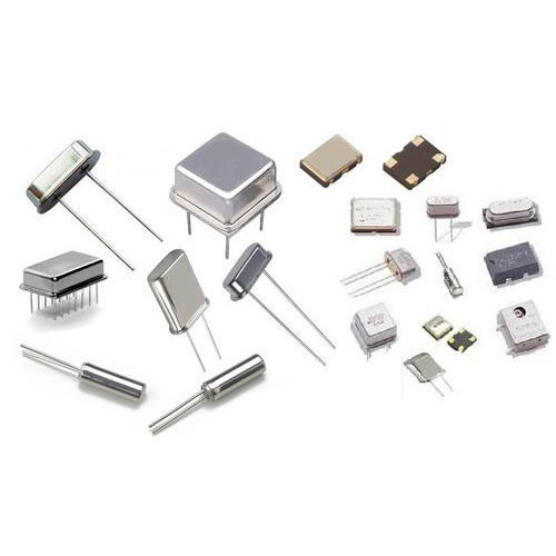
crystal oscillatoris an electronic oscillator circuit for the mechanical resonance of a vibrating crystal of a piezoelectric material; it will create an electrical signal of a given frequency, which is often used to provide a stable clock signal, for example: watches are used in digital integrated circuits to Provides a stable clock signal and is also used to stabilize the frequency of radio transmitters and receivers. Quartz crystals are primarily used in radio frequency (RF) oscillators. Quartz crystals are the most commonPiezoelectric Resonator Type, in oscillator circuits we use them, so it is calledcrystal oscillator。
Crystal Oscillator Circuitdesign must provideload capacitance; There are different types of oscillator electronic circuits used, namely: Linear Oscillator – Hartley Oscillator, Phase Shift Oscillator, Armstrong Oscillator, Clapp Oscillator, Colpitts Oscillator. Relaxation Oscillators – Royer Oscillators, Ring Oscillators, Multivibrators, and Voltage Controlled Oscillators (VCOs). Next, we will discuss the working principles and applications of crystal oscillators in detail.
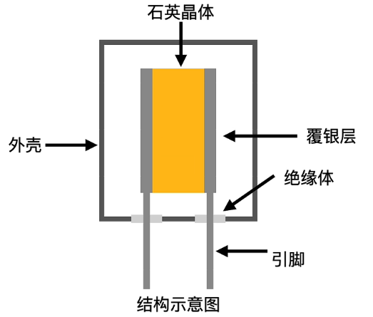
What are Quartz Crystals?
A quartz crystal has a very important property called the piezoelectric effect. When mechanical pressure is applied on the crystal surface, a voltage proportional to the mechanical pressure appears across the crystal. This voltage causes crystal distortion. The amount of distortion will be proportional to the applied voltage, and directly proportional to the AC voltage applied to the crystal, causing the crystal to vibrate at its natural frequency.
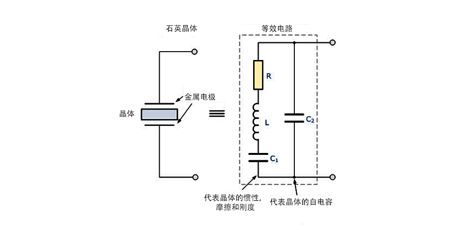
Quartz crystal circuit structure diagram
A quartz crystal circuit structure diagram represents the electronic symbol for a piezoelectric crystal resonator, and a quartz crystal in an electronic oscillator consisting of a resistor, inductor, and capacitor

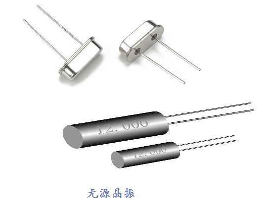
Crystal Oscillator - Figure 1
Crystal Oscillator - Figure 1 is a new 16MH 20psccrystal oscillator, which is a 16MHz operatingcrystal oscillator。
crystal oscillator
Usually, inCrystal Oscillator CircuitBipolar transistors or FETs are used in the construction of. This is because op amps can be used in different low frequency oscillator circuits below 100KHz, but op amps do not have an operating bandwidth. At higher frequencies matched to crystals above 1MHz, this will be a problem. To overcome this problem, Colpitts crystal oscillators were designed. It will work at a higher frequency. In this oscillator, the LC oscillation circuit that provides feedback oscillation has been replaced by a quartz crystal.
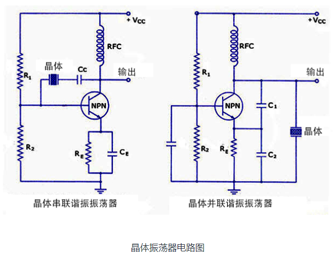
Crystal oscillator circuit diagram
How Crystal Oscillators Work
Crystal Oscillator CircuitUsually works according to the principle of the inverse piezoelectric effect. An applied electric field will produce mechanical deformations in some materials. Therefore, it exploits the mechanical resonance of a vibrating crystal made of piezoelectric material to generate an electrical signal at a specific frequency.
In general, quartz crystal oscillators are highly stable, consist of a good quality factor (Q), and their size is small and economically relevant. Therefore, quartz crystal oscillator circuits are superior compared to other resonators such as LC circuits, turning forks. Usually, in microprocessors and microcontrollers we use 8MHz crystal oscillator. The equivalent circuit also describes the crystalline action of a crystal. Just look at the equivalent circuit diagram shown above. The basic components used in the circuit, the inductance L represents the crystal quality, the capacitance C2 represents the compliance, C1 represents the capacitance formed due to the mechanical shaping of the crystal, the resistance R represents the internal structure friction of the crystal, and the quartz crystal oscillator circuit. The diagram includes two Resonance, such as series and parallel resonance, that is, two resonant frequencies.
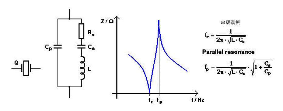
Schematic Diagram of Crystal Oscillator Operation
Series resonance occurs when the reactance generated by capacitor C1 is equal and opposite to the reactance generated by inductor L. fr and fp represent the series and parallel resonant frequencies respectively, and the values of 'fr' and 'fp' can be determined by using . The equation is shown above. Crystal Oscillator Working Schematic depicts equivalent circuit, graph of resonant frequency, formula for resonant frequency.
Uses of Crystal Oscillators
Generally, we know that in the design of microprocessors and microcontrollers, crystal oscillators are used to provide clock signals. For example let's consider 8051 microcontroller, in this particular controller an external crystal oscillator circuit will operate at the requisite 12MHz even though that 8051 microcontroller (based on the model) is capable of 40MHz (maximum) Work must also provide 12MHz In most cases, since a machine cycle 8051 takes 12 clock cycles, this gives an effective cycle rate of 1MHz (based on a 12MHz clock) to .33MHz (based on a maximum 40MHz clock). This particular crystal oscillator has a period rate of 1MHz to 3.33MHz and is used to generate the clock pulses required for the synchronization of all internal operations.
Intelligent Recommendation
Crystal Oscillator
Article Directory 【 1. Structure 】 【 2. Principle 】 【 3. Equivalent circuit 】 【4. Active crystal oscillator】 effect Provides a clock frequency for the CPU, which can execute instructions as a time ref...
(Reproduced) STM32 external crystal oscillator circuit design and matching
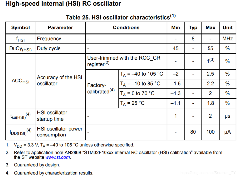
(Reprinted from:) STM32 clock source STM32F103 has two main clock solutions, one is HSI (internal high-speed clock) relying on internal RC oscillator, the other isHSE(External high-speed clock). Inter...
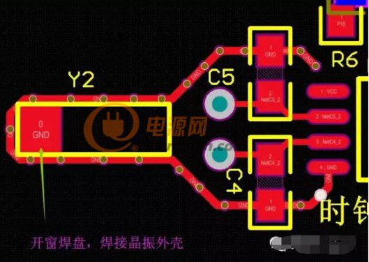
【PCB Design】Crystal Oscillator Clock Circuit Layout Design
Clock circuit design of PCB modular layout series (crystal oscillator, crystal) 1. Crystal In a circuit system, a clock is essential part. Like the function of the human heart, if the clock of the cir...
[Circuit Design] Reference Guide for Crystal Oscillator Selection and Load Capacitance Matching
[Circuit Design] Reference Guide for Crystal Oscillator Selection and Load Capacitance Matching First of all, let me declare that this content is collected and compiled by myself, and it is not for ex...

Summary of STM32 USB virtual serial port debugging (internal crystal oscillator, external crystal oscillator configuration, hardware circuit description, test method)
table of Contents 1, reference link: 2, virtual serial port hardware description 2.1, the program does not need to configure the hardware design: D + directly connected to the 3.3V pull-up resistor. 2...
More Recommendation
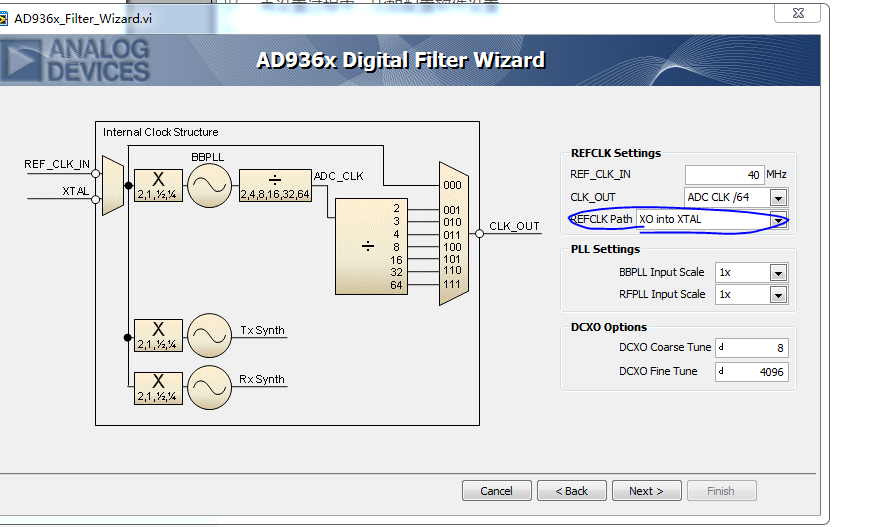
AD9361 crystal oscillator crystal selection
When actually using the AD9361, sometimes the hardware circuit design has two options for the reference crystal, one is crystal and the other is crystal During the setup process, such as configuring s...

RTC-crystal oscillator
The main indicator of crystal oscillator Phase noise It is mainly the deviation of the crystal frequency from the frequency in a short period, which can be obtained by frequency domain conversion. The...

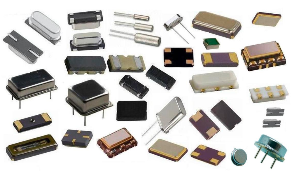
The difference between crystal and oscillator
Transfer from The difference between crystal and crystal: 1) Crystal oscillator is the abbreviation of active crystal oscillator, also called oscillator. The English name is oscillator. A crystal is a...
How crystal oscillator works
Crystal or Jingzhen, or silly? Crystal is short for crystal resonator (Crystal), also known asPassive crystal. Generally, it is an electronic component that uses the piezoelectric effect of quartz cry...
Explanation and application of crystal oscillator
1. The concept of crystal oscillator The crystal oscillator refers to the slice (referred to as the wafer) cut from a piece of quartz crystal at a certain azimuth angle. The quartz crystal resonator i...