STM32---------ADC (Analog/Digital Converter)
tags: stm32 Single chip computer Internet of Things Embedded
Article Directory
Preface
STM32---------ADC (Analog/Digital Converter)
Tip: The following is the main content of this article, and the following cases are for reference
1. ADC definition
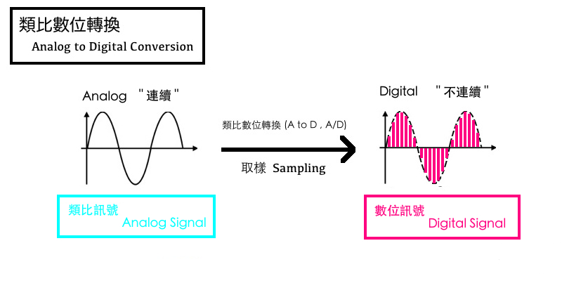
ADC, abbreviation of Analog-to-Digital Converter, refers to an analog//digital converter or analog-to-digital converter. It refers to a device that converts continuously changing analog signals into discrete digital signals. Real-world analog signals, such as temperature, pressure, sound or images, need to be converted into digital forms that are easier to store, process and emit. An analog/digital converter can implement this function and it can be found in a variety of different products.
2. Analog signal
analog signal
Temperature: Temperature sensor, DHT11
Humidity: Humidity sensor, DHT11
Sound: Audio chip for recording, WM8906
Image: Sony IMX386/IMX283 sensor
Sensor converts analog signals into digital signals
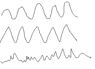
An analog signal means that the numerical value is continuous, that is, the number of numerical values is infinitely large.
3. Digital signal
Digital Signal:
HD digital TV, MP3, JPG files
Features: represented by binary, the values are discrete and discontinuous
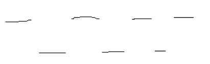
Digital signals means that the values are discontinuous, and the number of values is limited.
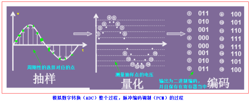
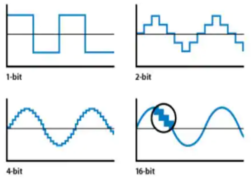
IV. The process of analog-to-digital conversion
V. Characteristics
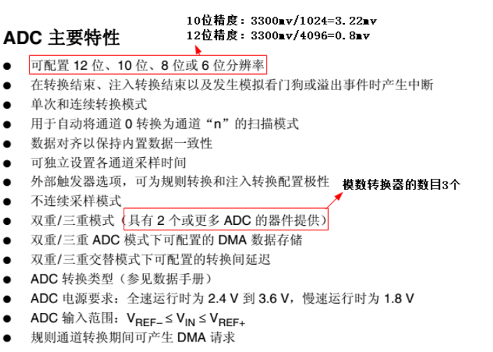
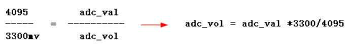
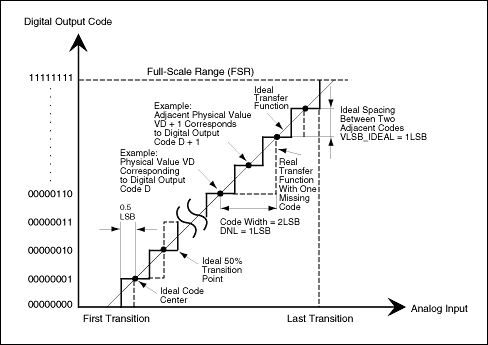
12-bit accuracy: 3300mv/4096=0.8mv, that is, the ADC can only distinguish it as long as the voltage value changes by ±0.8mv.
10-bit accuracy: 3300mv/1024=3.22mv, that is, the ADC can only distinguish it as long as the voltage value changes by ±3.22mv.
8-bit accuracy: 3300mv/256=12mv, which means that the ADC can only distinguish it as long as the voltage value changes by ±12mv.
6-bit accuracy: 3300mv/64=51.5625mv, that is, the ADC can only distinguish it as long as the voltage value changes by ±51.5625mv.
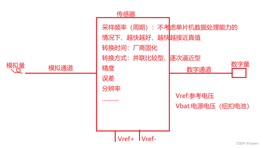
6. Hardware circuit
1. Schematic diagram
The VREF pin is the reference voltage, which can be understood as determining the maximum value measured by the ADC.
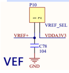
The connection of the VREF pin determines the current voltage measurement range of 0V~3.3V. Generally speaking, this pin cannot exceed the power supply voltage of the chip!
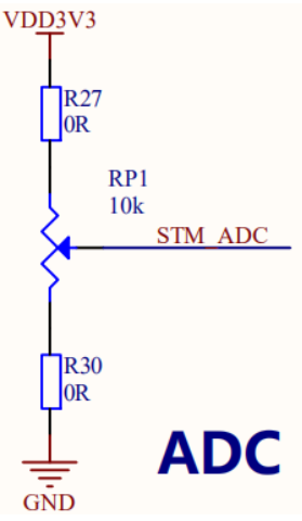
2. Pins used for adjustable resistors
3. The ADCs supported by different pins are different.
1.
The PC0 pin can use ADC1, ADC2 or ADC3 converters, using the 10th input channel!
2.

The PF10 pin can only use the ADC3 converter, using the 8th input channel!
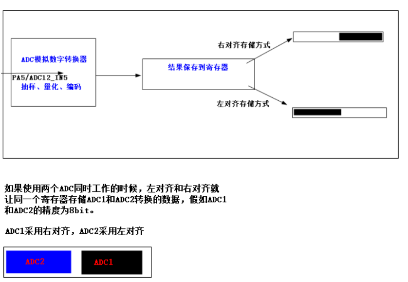
4. Storage alignment method
7. Thinking questions
Why do the result values obtained through ADC hardware still have to be converted into voltage values? What is the basis?
8. Source code download
Summarize
The above is what we are going to talk about today. This article only briefly introduces the use of ADC, and some other usage modules of STM32. Please follow the blogger’s other articles or follow the blogger to wait for subsequent releases.
Intelligent Recommendation
Basic working principle of the ADC analog-to-digital converter
Natural world has many natural analog signals, such as people's voice sizes, speed. The embedded processor or the microcontroller system can only process numbers. If you want to study people's voice s...
ADC modulus converter (STM32 series)
Cortex-M4-Modeling Converter Overview of Model Converter Model converter use The MCU (single -chip machine) species can only process the number of digital quantity, but when the external input simulat...
ADC of STM32 notes (analog-to-digital conversion)
Write in front: The purpose of this article is to summarize the backup and facilitate future queries. Since it is a personal summary, if you are wrong, please correct me; in addition, most of the cont...

Convert ADC analog signal to digital signal in STM32
It is not unfamiliar to convert analog signals to digital signals. The analog signal is a continuously changing signal. The ADC converts the continuous signal into a corresponding digital signal throu...

ESP32 Study Notes (4) ADC-Analog to Digital Converter
ADC - Analog to Digital Converter Overview ESP32 integrates two 12-bit successive approximation analog-to-digital converters (SARADC), managed by five dedicated converter controllers. It supports meas...
More Recommendation

STM8S003xx study notes (1): analog / digital converter (ADC)
Although STM8S003F has been used for a year, but some of the knowledge is still not very detailed, starting from today to do a complete study of the chip information. This article serves as a study no...
INL/DNL measurement of high-speed analog-to-digital converter (ADC)
Abstract: Although integral nonlinearity and differential nonlinearity are not the most important parameters of high-speed and high-dynamic performance data converters, they are of great significance ...

IoT STM32 development six (ADC analog-to-digital conversion)
STM32-ADC analog-to-digital conversion abstract: STM32-ADC analog-to-digital conversion overview STM32-Single channel acquisition example STM32-Multi-channel acquisition example STM32-ADC analog-to-di...
Simple understanding of ADC analog-to-digital conversion not based on STM32
We know that the IO of the single-chip microcomputer can detect the binary high and low levels (that is, digital signals of 0 or 1), such as judging whether the button is pressed by the l...
STM32 learning note (13) - analog to digital conversion ADC
This month has been busy preparing for the exam, has been tested for half of the subject, and I have a thief wrote this article. Because I didn't have test, I was estimated to have a long time. STM32 ...