S32K series S32K144 study notes - clock
tags: S32K144 clock Clock tree S32K series S32K144 clock register operation
Take the MCU as S32K144, develop the platform S32DSworkspace, clock configuration, pick up a few configurations and write and write easily. If there is an error, please help me to point out, thank you!
Related clock configuration code:
#include "S32K144.h" /* include peripheral declarations S32K144 */
#include "s32_core_cm4.h"

void WDOG_disable (void)
{
	WDOG->CNT=0xD928C520; //Unlock the watchdog
	 WDOG->TOVAL=0x0000FFFF; //Configure time to maximum
	 WDOG->CS = 0x00002100; //Close the watchdog
}

void SOSC_init_8MHz(void)
{
	SCG->SOSCDIV=0x00000101;  /* SOSCDIV1 & SOSCDIV2 =1: divide by 1 */
	SCG->SOSCCFG=0x00000024;  /* Range=2: Medium freq (SOSC betw 1MHz-8MHz)*/
                        	  /* HGO=0:   Config xtal osc for low power */
                              /* EREFS=1: Input is external XTAL */
	while(SCG->SOSCCSR & SCG_SOSCCSR_LK_MASK); /* Ensure SOSCCSR unlocked */
	SCG->SOSCCSR=0x00000001;  /* LK=0:          SOSCCSR can be written */
                        	  /* SOSCCMRE=0:    OSC CLK monitor IRQ if enabled */
                        	  /* SOSCCM=0:      OSC CLK monitor disabled */
                        	  /* SOSCERCLKEN=0: Sys OSC 3V ERCLK output clk disabled */
                        	  /* SOSCLPEN=0:    Sys OSC disabled in VLP modes */
                        	  /* SOSCSTEN=0:    Sys OSC disabled in Stop modes */
                        	  /* SOSCEN=1:      Enable oscillator */
	while(!(SCG->SOSCCSR & SCG_SOSCCSR_SOSCVLD_MASK)); /* Wait for sys OSC clk valid */
}


void SPLL_init_160MHz(void)
{
	while(SCG->SPLLCSR & SCG_SPLLCSR_LK_MASK); /* Ensure SPLLCSR unlocked */
	SCG->SPLLCSR = 0x00000000;  /* SPLLEN=0: SPLL is disabled (default) */
	SCG->SPLLDIV = 0x00000302;  /* SPLLDIV1 divide by 2; SPLLDIV2 divide by 4 */
	SCG->SPLLCFG = 0x00180000;  /* PREDIV=0: Divide SOSC_CLK by 0+1=1 */
                          		/* MULT=24:  Multiply sys pll by 4+24=40 */
                          		/* SPLL_CLK = 8MHz / 1 * 40 / 2 = 160 MHz */
	while(SCG->SPLLCSR & SCG_SPLLCSR_LK_MASK); /* Ensure SPLLCSR unlocked */
	SCG->SPLLCSR = 0x00000001; /* LK=0:        SPLLCSR can be written */
                         	   /* SPLLCMRE=0:  SPLL CLK monitor IRQ if enabled */
                         	   /* SPLLCM=0:    SPLL CLK monitor disabled */
                         	   /* SPLLSTEN=0:  SPLL disabled in Stop modes */
                         	   /* SPLLEN=1:    Enable SPLL */
 	while(!(SCG->SPLLCSR & SCG_SPLLCSR_SPLLVLD_MASK)); /* Wait for SPLL valid */
}

void NormalRUNmode_40MHz (void)
{
	/* Change to normal RUN mode with 8MHz SOSC, 80 MHz PLL*/
	SCG->RCCR=SCG_RCCR_SCS(6)     /* PLL as clock source*/
	|SCG_RCCR_DIVCORE(0b11)       /* DIVCORE=3, div. by 4: Core clock = 160/4 MHz = 40 MHz*/
	|SCG_RCCR_DIVBUS(0b11)        /* DIVBUS=3, div. by 4: bus clock = 160/4 MHz = 40 MHz*/
	|SCG_RCCR_DIVSLOW(0b111);     /* DIVSLOW=7, div. by 8: SCG slow, flash clock= 160/8 MHz = 20MHZ*/
	while (((SCG->CSR & SCG_CSR_SCS_MASK) >> SCG_CSR_SCS_SHIFT ) != 6) {}
    /* Wait for sys clk src = SPLL */
}
int main(void)
{

	 WDOG_disable(); //Close the watchdog

	 SOSC_init_8MHz(); //Configure the system oscillator to external 8MHZ
	 SPLL_init_160MHz(); //Configure SPLL to 160 MHz using SOSC 8MHZ
	 NormalRUNmode_40MHz(); //Configure the series clock 40MHz, 40MHz bus clock

	while(1)
	{
		/*Add your own code*/
	}
	return 0;
}
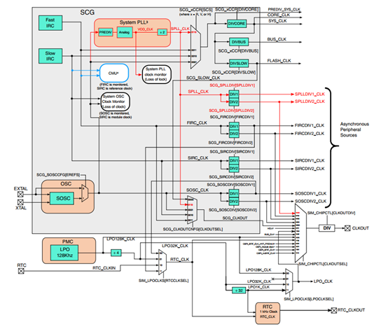
S32K144 clock tree:
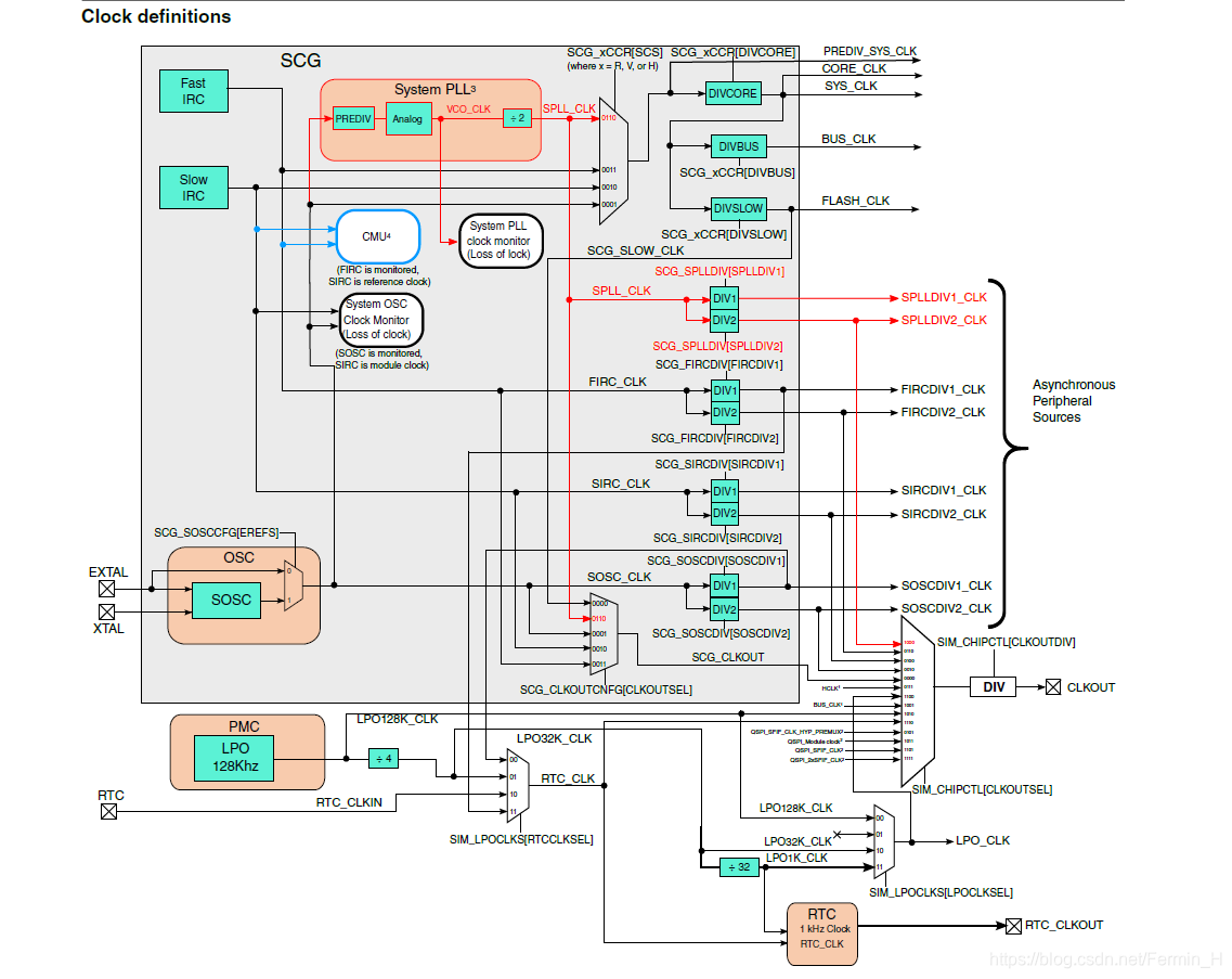
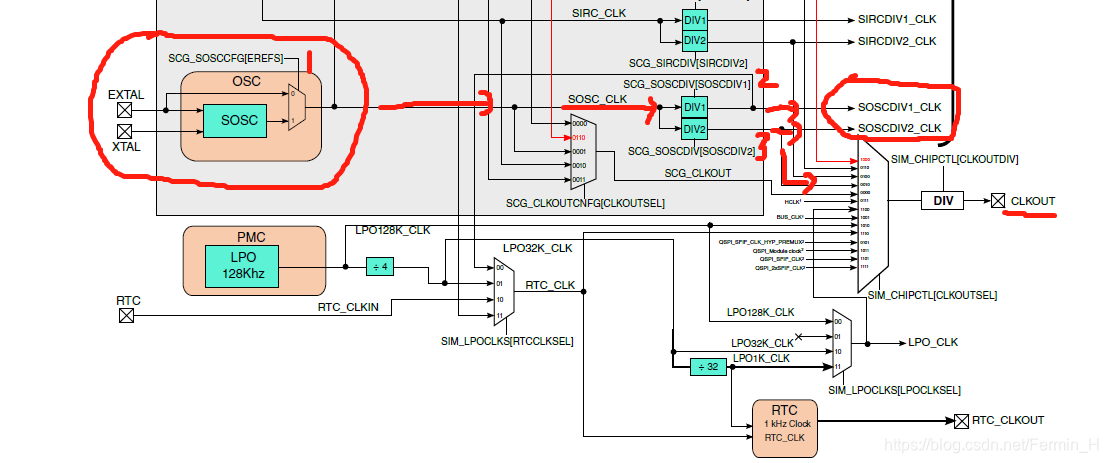
1, void SOSC_init_8MHz (void), the function configuration is the path shown in the following figure, and finally get SOCSDIV1_CLK, SOCSDIV2_CLK, and other forks to other branches; need to be configured There are three registers SCG_SOSCCSR (Control Status Register), SCG_SOSCDIV (Division Register), SCG_SOSCCFG (Oscillator Configuration Register)
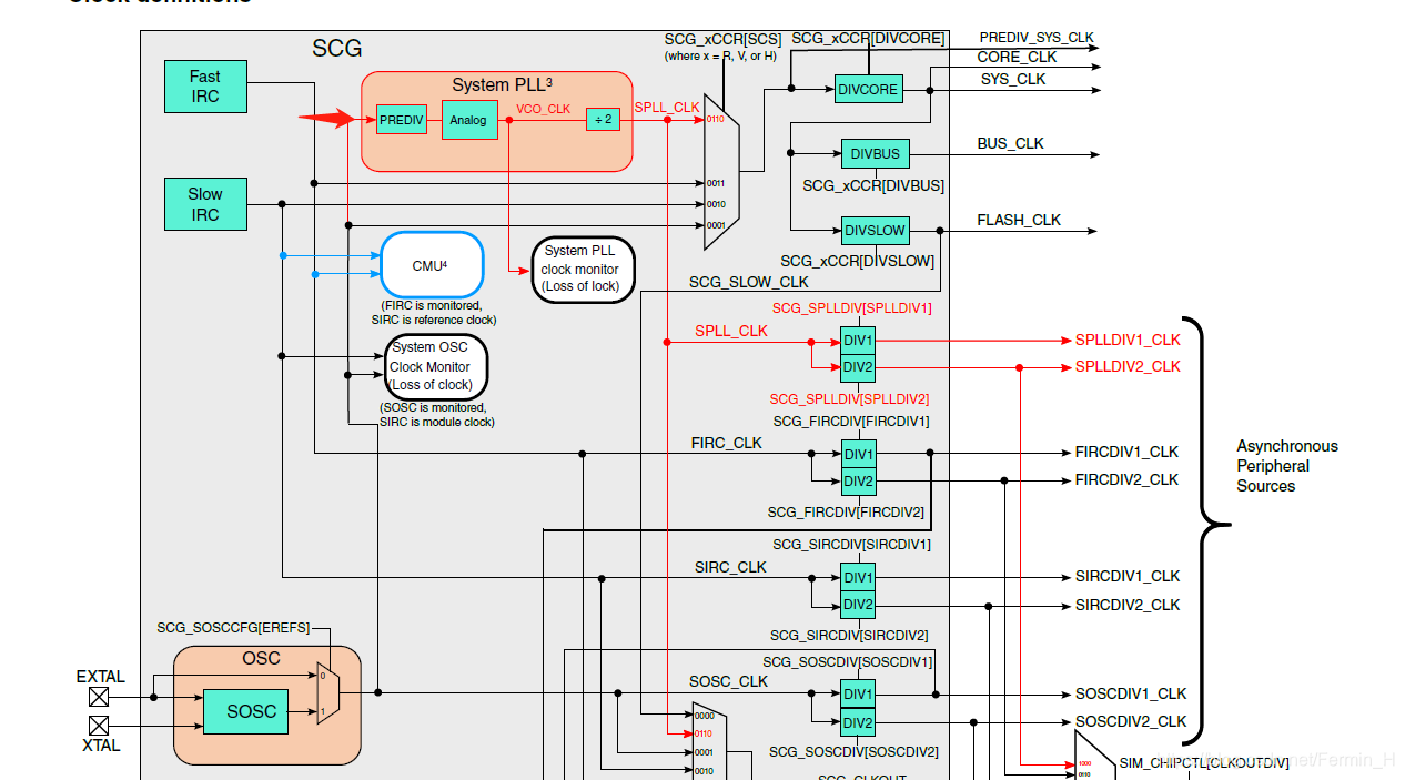
2, void SPLL_init_160MHz(void), the function configuration is the path shown in the figure below, and finally get SPLLDIV1_CLK, SPLLDIV2_CLK, SPLL_CLK; there are three registers SCG_SPLLCSR (PLL control status register) to be configured. ), SCG_SPLLDIV (PLL Divider Register), SCG_SPLLCFG (PLL Configuration Register)
Calculation formula for SPLL_CLK:
SPLL_CLK = (VCO_CLK)/2
VCO_CLK = SOSC_CLK/(PREDIV + 1) *(MULT + 16)
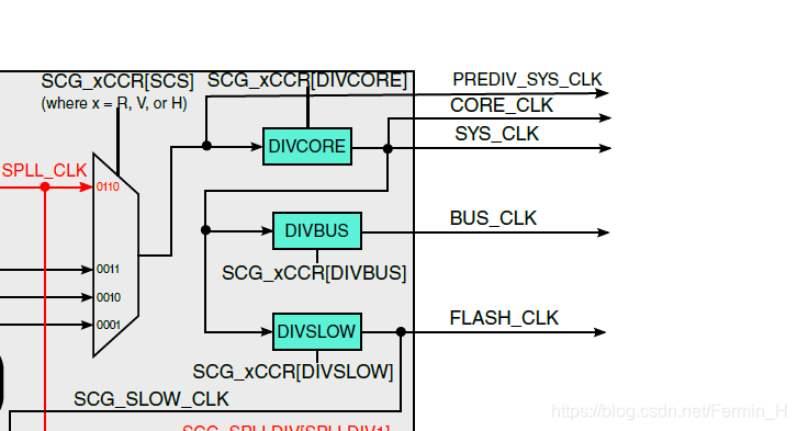
3, void NormalRUNmode_40MHz(void), function configure SCG_RCCR (run clock control register), get FLASH_CLK, BUS_CLK, CORE_CLK
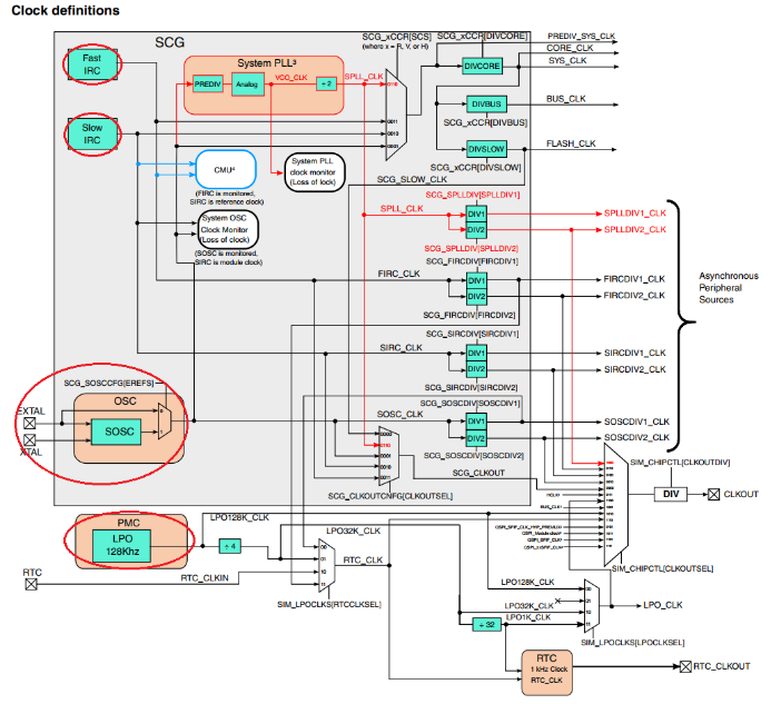
You can also see the following configurations:
The clock selection of the specific function module of the chip can also be seen in some views, such as the following one. For more details, please see S32-RM.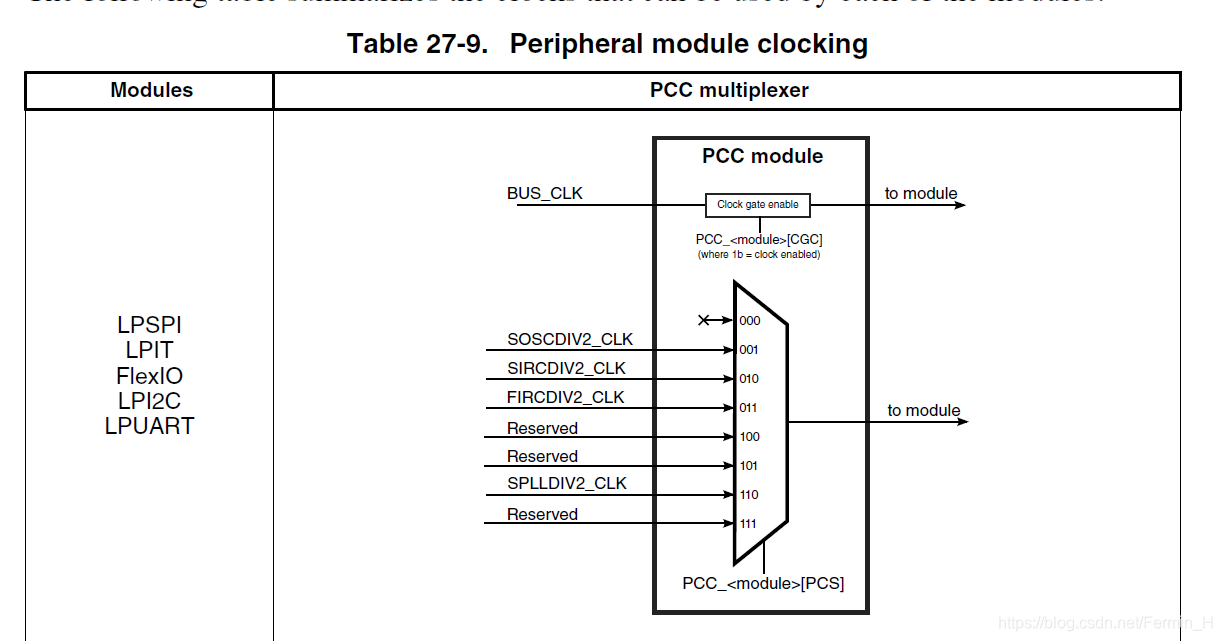
Intelligent Recommendation

S32K144 study notes: 23 watchdog
23.1 On-chip watchdog specifications 23.1.1 Watchdog Clock The watchdog module has the following optional clock sources • Internal low-power oscillator (LPO_CLK) • Internal low-speed IRC clo...
S32K--UART configuration and use study notes (SDK3.0)
Use the official development board of NXP S32K148EVB, UART1 pin RX-PTC6 TX-PTC7. ProcessorExpert configuration I/O configuration Add UART module Select uart right click to add module Configure ...
S32K--Timer configuration and use study notes (SDK3.0)
Use the official development board of NXP S32K148EVB. ProcessorExpert configuration Add lpit module Right-click lpit to add a module Configure lpit Time unit us Completion code Ge...
S32K--PWM configuration and use study notes (SDK3.0)
Use NXP S32K148EVB official development board, PWM output port is PTE22. ProcessorExpert configuration Add PWM module Right click to add the ftm_pwm module to the project C...
S32K--ADC configuration and use study notes (SDK3.0)
Use the official development board of NXP S32K148EVB, and the AD collection port is PTC28. ProcessorExpert configuration Click PTC28 to select it (I don't know if this step is useful, it is filled in ...
More Recommendation
S32K144 study notes-Piao Ding Jie Niu
S32K14X series MCU study notes #S32K14X Series MCU peripheral configuration and advanced This part is probably the basic module of all MCUs coming out in recent years. 1、clock: It is the basis of the ...
S32k144 (2) clock configuration
table of Contents 1 Introduction 2, clock tree 2.1, clock source 2.2, clock mode 2.3, clock frequency of each module 3, register 3.1、SCG_VERID:Version ID Register 3.2、SCG_PARAM:Parameter Registe...
S32K144 clock configuration and clock view
S32K144 clock configuration and clock view Take S32K144 as configuration test 1. Clock tree introduction Input part: S32K144 has four clock sources, as the clock tree in the above figure has been circ...

S32K clock module and serial communication
Overview When the S32K series chip is developed, although the official provides SDK and has now updated to version 4.02, there is a processor excert one-button configuration, the clock, peripherals, i...
S32K--input capture (FTM_IC) configuration and use study notes (SDK3.0)
Use NXP S32K148EVB official development board, UART1 pin RX-PTC6 TX-PTC7. ProcessorExpert configuration I/O configuration Select FTM0 channel 0 and set PTD15 as input to collect PWM frequency and duty...