Introduction to the FEE module of AUTOSAR
tags: notes
FEE (Flash EEPROM Emulation), namely Flash emulation EEPROM. Why use Flash to simulate EEPROM? Let's look at the difference between the two below.
Non-volatile memory, non-volatile memory, is the memory that can save data after power failure. We know that both Flash and EEPROM belong to this type of memory, but there are still many differences between them, mainly in the following aspects:
1. Different erasing methods
Flash: Divided into several pages, the entire chip will be erased when erasing. When writing, the bit must be 1 to write in. Therefore, every time you modify data in Flash, you must erase and then write. Into.
EEPROM: It can be modified directly without erasing before writing, and single byte can be modified, and the reading and writing speed is slower.
2. Number of erasing and writing
Flash is less than EEPROM.
3. From an economic point of view
Many chips cancel EEPROM, and use Flash to simulate EEPROM instead of EEPROM to reduce costs.
4. Different needs
Flash: generally store some data that is not easy to change, such as some factory data (VIN code) of the vehicle, etc., because these data do not need to be changed frequently, so they can be stored in Flash.
EEPROM: generally stores some data that is easy to change, such as DTC in the fault diagnosis. If it is stored in the Flash, it will continue to erase and write the Flash, and the erase area is large, which is not conducive to operation.
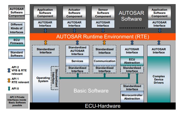
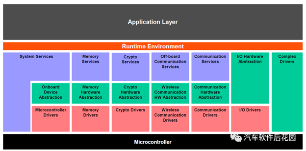
In the AUTOSAR architecture, FEE is in the Memory Hardware Abstraction, as shown in the following figure:

Flash simulation EEPROM mechanism:
We know that Flash is operated by page. This method is more suitable for Flash with larger sectors. Assuming that the Data Flash of our MCU has two sectors, mark the two sectors as logical sector 1 (logical sector 1). sector 1) and logical sector 2 (logical sector 2). Suppose we want to use Flash to emulate EEPROM to store DTC, we all know that DTC is a very small data, but the update may be more frequent, as shown below: First of all, logical sector 1 (logical sector 1) is blank waiting for us to write data, belonging to the active sector (Actived).
Assuming that Flash can write 8 bytes at a time, we can divide it like this: the first 4 bytes are used to store the DTC identifier, and the last 4 bytes are used to store the specific DTC (this is an assumption, the programmer can design the storage length by himself, etc. ), every time the DTC is updated, we continue to update the data in the unwritten space, until the logical sector 1 (logical sector 1) is full, we copy the latest DTC data into the logical sector 2 (logical sector 2) ) Inside, and then erase the entire slice of logical sector 1 (logical sector 1). At this time, the status of logical sector 1 (logical sector 1) becomes (Not Actived) to be a work area, and logical sector 2 (logical sector 2) Become an (Actived) working area, wait until logical sector 2 (logical sector 2) is full, then copy the latest data to logical sector 1 (logical sector 1), and then erase logical sector 2 (logical sector 2), so Repeatedly back and forth.
The general workflow is like this. Of course, if there are more Flash slices, it is not limited to dividing the logical sector into two. Now some chip manufacturers such as ST have provided Flash emulation EEPROM interface on one of their automotive-grade MCU SPC560 series. Programmers only need to know this mechanism, configure the logical sector in SPC5Studio, and use it directly after generating the code. can.
Intelligent Recommendation
Functions of each module of AUTOSAR
Functions of each module of AUTOSAR ①Ethernet Transceiver (Ethtrcv): Ethernet transceiver ②UdpNm (network management): network management Primarily designed as an optional feature, intended to work wi...
AUTOSAR diagnostic Introduction
AUTOSAR diagnostic Introduction The main goal of AUTOSAR architecture there are three: Establishment of an independent hardware layered software architecture Provide methodology for the implementation...

Introduction of AUTOSAR software components
In AUTOSAR, application software is composed of a series of interactive software components. In the development process of application software based on AUTOSAR, software components are the foundation...

AUTOSAR introduction and tool supplier
1. Introduction to AUTOSAR Software in the field of automotive electronics is mainly embedded software. Therefore, its development stage is similar to the software development of other embedded system...
Introduction to CP AUTOSAR
Embedded systems do not support hardware abstraction, which makes us replace each time with a new processor. All need to re-development of the underlying software. The autosar organization was establi...
More Recommendation
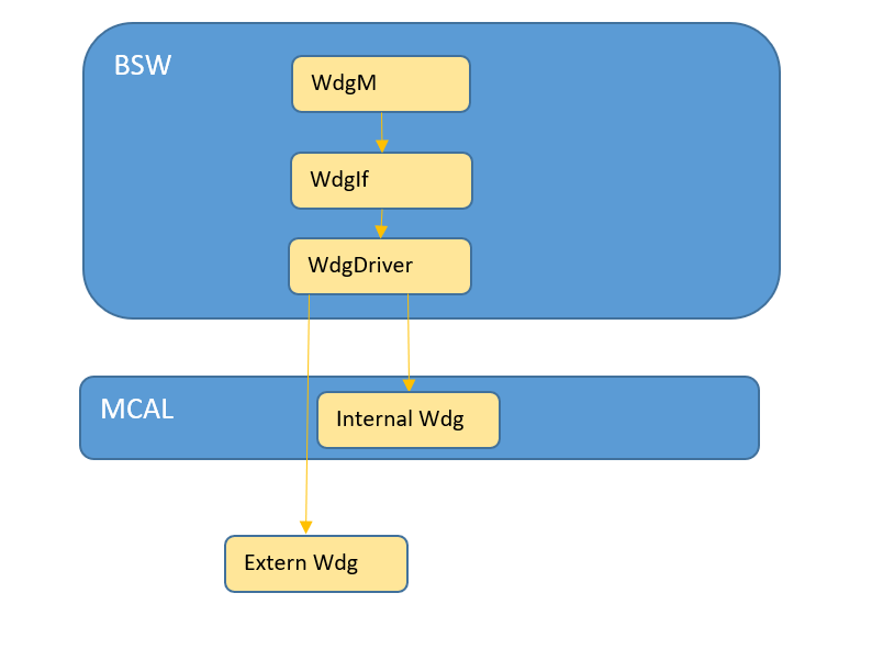
AUTOSAR Wdg basic introduction
Introduction to WdgM 1. Overview of WdgM functions 2. WdgM detailed function introduction TBD 3. Introduction of Vector-based WdgM simple configuration items TBD WdgIf introduction TBD Wdg introductio...
Introduction to AUTOSAR Software Architecture
What is AUTOSAR AUTOSAR’s full name is AUTomotive Open System Architecture, literally translated as automotive open system architecture. It is jointly established by global automobile manufactur...
Introduction to AUTOSAR BSW
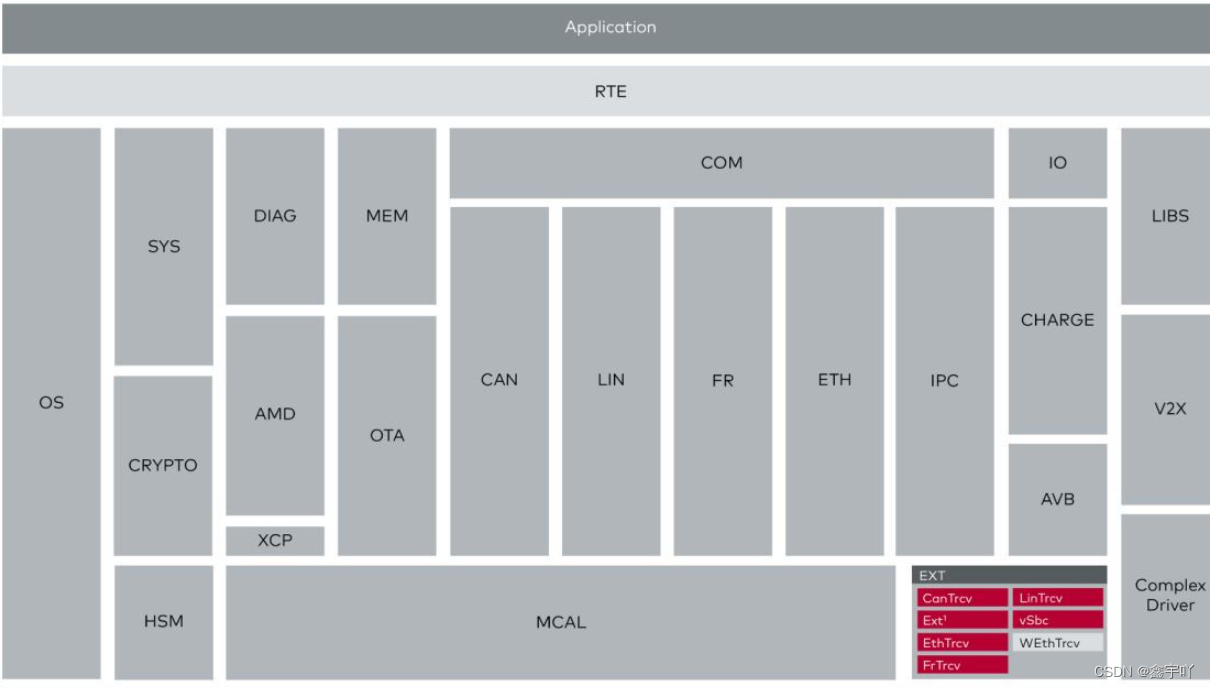
BSW architecture The previous article mentioned that the basic software layer BSW includes the microprocessor abstraction layer (MCAL), the ECU abstraction layer, the service layer, and complex driver...
Introduction to Autosar Diagnostics Knowledge
AutosAr Diagnostics There are three main targets of the Autosar architecture: Establish a hierarchical software architecture independent of hardware To implement application methodology, including the...
AutoSar DataType Introduction
Foreword After reading the basic configuration, I found that the content of Autosar's DataType is more complicated, so open a chapter alone to record it. AutoSar DataType Introduction Foreword I. Basi...